How to Use ASR PRO 2.0: Examples, Pinouts, and Specs
Introduction
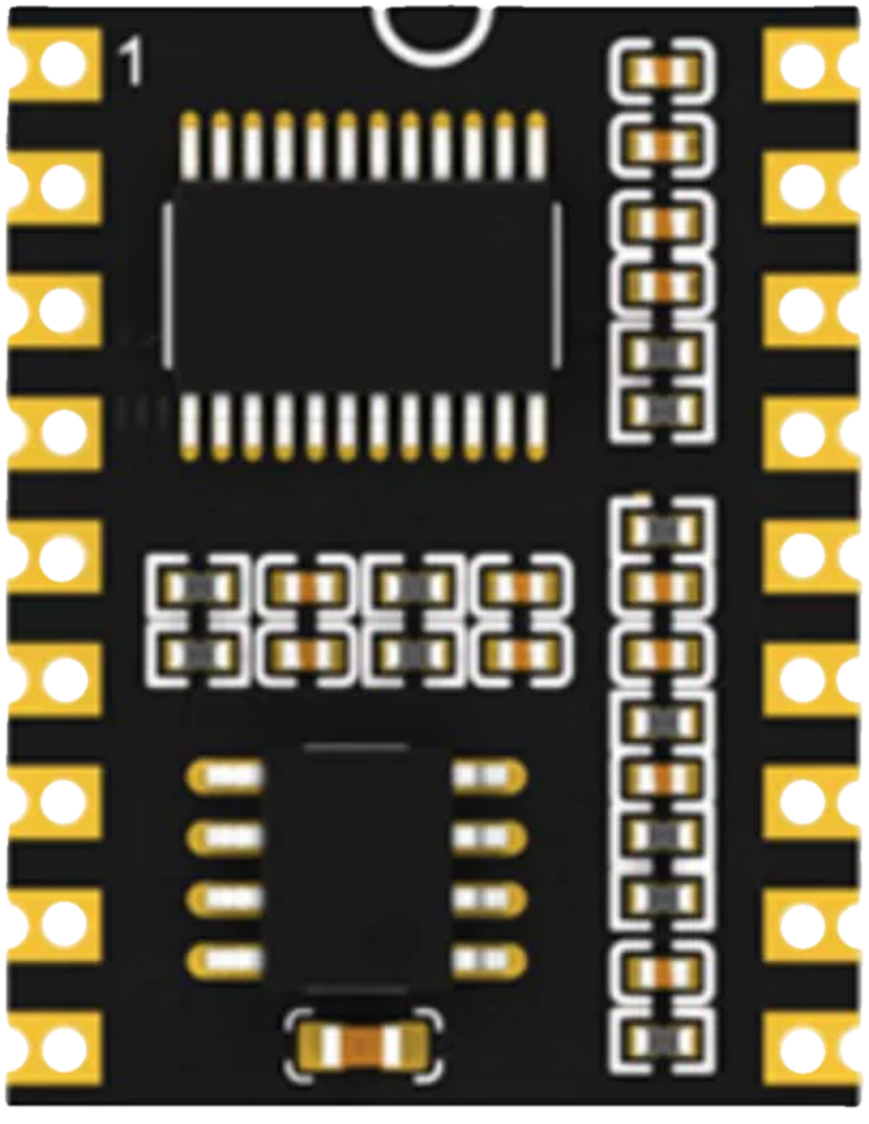
The ASR PRO 2.0 is an advanced audio signal processor designed for professional audio applications. It offers real-time audio analysis, dynamic range control, and customizable settings to ensure optimal sound quality. This component is ideal for use in audio mixing consoles, live sound reinforcement systems, and studio recording setups. Its robust design and versatile features make it a go-to solution for audio engineers and sound designers.
Explore Projects Built with ASR PRO 2.0
Explore Projects Built with ASR PRO 2.0
Common Applications:
- Live sound reinforcement for concerts and events
- Studio recording and mixing
- Audio mastering and post-production
- Public address (PA) systems
- Broadcast audio processing
Technical Specifications
Key Technical Details:
| Parameter | Specification |
|---|---|
| Operating Voltage | 5V DC |
| Power Consumption | 500 mW |
| Signal Processing | 32-bit floating-point DSP |
| Frequency Response | 20 Hz – 20 kHz |
| Signal-to-Noise Ratio (SNR) | >100 dB |
| Input Impedance | 10 kΩ |
| Output Impedance | 600 Ω |
| Audio Channels | Stereo (2 channels) |
| Control Interface | I2C, UART |
| Dimensions | 50 mm x 30 mm x 10 mm |
Pin Configuration and Descriptions:
| Pin Number | Pin Name | Description |
|---|---|---|
| 1 | VCC | Power supply input (5V DC) |
| 2 | GND | Ground connection |
| 3 | AUDIO_IN_L | Left channel audio input |
| 4 | AUDIO_IN_R | Right channel audio input |
| 5 | AUDIO_OUT_L | Left channel audio output |
| 6 | AUDIO_OUT_R | Right channel audio output |
| 7 | SDA | I2C data line for communication |
| 8 | SCL | I2C clock line for communication |
| 9 | TX | UART transmit line for serial communication |
| 10 | RX | UART receive line for serial communication |
| 11 | RESET | Active-low reset pin to restart the processor |
| 12 | CONFIG | Configuration pin for selecting preset audio profiles (low/high logic) |
Usage Instructions
How to Use the ASR PRO 2.0 in a Circuit:
- Power Supply: Connect the VCC pin to a stable 5V DC power source and the GND pin to ground.
- Audio Input: Feed the left and right audio signals into the
AUDIO_IN_LandAUDIO_IN_Rpins, respectively. - Audio Output: Connect the processed audio signals from
AUDIO_OUT_LandAUDIO_OUT_Rto your output device (e.g., speakers or amplifiers). - Control Interface: Use the I2C or UART interface to configure the processor settings. For I2C, connect the
SDAandSCLpins to the corresponding lines on your microcontroller. For UART, connect theTXandRXpins. - Reset and Configuration: Use the
RESETpin to restart the processor if needed. TheCONFIGpin can be used to toggle between preset audio profiles.
Important Considerations:
- Ensure that the input audio signals do not exceed the maximum input voltage range to avoid distortion or damage.
- Use shielded cables for audio connections to minimize noise and interference.
- If using the I2C interface, ensure that pull-up resistors (typically 4.7 kΩ) are connected to the
SDAandSCLlines. - For UART communication, ensure that the baud rate matches the settings of your microcontroller or host device.
Example: Connecting ASR PRO 2.0 to an Arduino UNO
Below is an example of how to configure the ASR PRO 2.0 using an Arduino UNO via the I2C interface:
#include <Wire.h> // Include the Wire library for I2C communication

#define ASR_PRO_ADDRESS 0x40 // I2C address of the ASR PRO 2.0

void setup() {
  Wire.begin(); // Initialize I2C communication
  Serial.begin(9600); // Initialize serial communication for debugging

  // Configure the ASR PRO 2.0
  Wire.beginTransmission(ASR_PRO_ADDRESS);
  Wire.write(0x01); // Example: Send a command to enable dynamic range control
  Wire.endTransmission();

  Serial.println("ASR PRO 2.0 initialized and configured.");
}

void loop() {
  // Example: Monitor audio processing status
  Wire.requestFrom(ASR_PRO_ADDRESS, 1); // Request 1 byte of data
  if (Wire.available()) {
    byte status = Wire.read(); // Read the status byte
    Serial.print("Processor Status: ");
    Serial.println(status, HEX); // Print the status in hexadecimal format
  }

  delay(1000); // Wait for 1 second before the next status check
}
Best Practices:
- Always test the audio signal processor in a controlled environment before deploying it in a live setup.
- Regularly update the firmware of the ASR PRO 2.0 if updates are available from the manufacturer.
- Use proper heat dissipation methods if the processor is used in high-power applications.
Troubleshooting and FAQs
Common Issues and Solutions:
No Audio Output:
- Cause: Incorrect wiring or no power supply.
- Solution: Verify all connections, ensure the power supply is stable, and check the input/output wiring.
Distorted Audio:
- Cause: Input signal level too high or incorrect configuration.
- Solution: Reduce the input signal level and verify the configuration settings.
I2C Communication Failure:
- Cause: Missing pull-up resistors or incorrect I2C address.
- Solution: Add pull-up resistors to the
SDAandSCLlines and confirm the I2C address.
Processor Not Responding:
- Cause: The processor is stuck or improperly initialized.
- Solution: Use the
RESETpin to restart the processor and reinitialize it.
FAQs:
Q: Can the ASR PRO 2.0 process mono audio signals?
- A: Yes, connect the mono signal to either the left or right input channel and leave the other channel unconnected.
Q: What is the default baud rate for UART communication?
- A: The default baud rate is 9600 bps.
Q: Can I use the ASR PRO 2.0 with a 3.3V microcontroller?
- A: Yes, but you will need a level shifter to interface the 3.3V logic with the 5V logic of the ASR PRO 2.0.
Q: Are there any preset audio profiles available?
- A: Yes, the
CONFIGpin can be used to toggle between preset profiles. Refer to the manufacturer's documentation for details.
- A: Yes, the
This concludes the documentation for the ASR PRO 2.0.