Cirkit Designer Logo
Cirkit Designer
Your all-in-one circuit design IDE
Home / 
Component Documentation

How to Use TTP-229: Examples, Pinouts, and Specs

Image of TTP-229
Cirkit Designer LogoDesign with TTP-229 in Cirkit Designer

Introduction

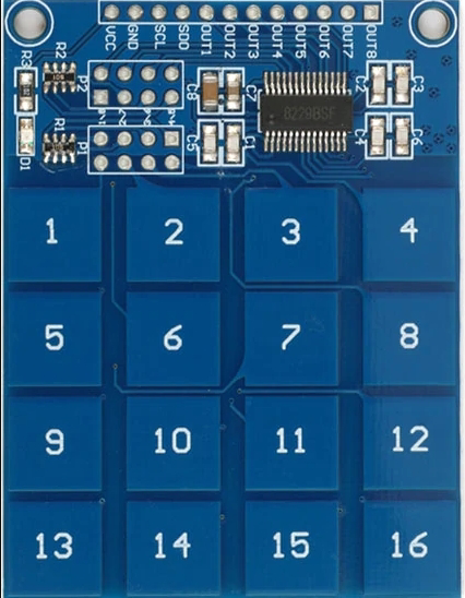
The TTP-229 is a capacitive touch sensor IC manufactured by Tontek Design Technology Ltd. It is designed to provide touch-sensitive control for electronic devices, enabling a modern and intuitive user interface. The IC supports up to 16 touch keys, making it suitable for applications requiring multiple touch inputs. Its compact design, low power consumption, and ease of integration make it a popular choice for a wide range of projects.

Explore Projects Built with TTP-229

Use Cirkit Designer to design, explore, and prototype these projects online. Some projects support real-time simulation. Click "Open Project" to start designing instantly!
Satellite-Based Timing and Navigation System with SDR and Atomic Clock Synchronization
Image of GPS 시스템 측정 구성도_Confirm: A project utilizing TTP-229 in a practical application
This circuit appears to be a complex system involving power supply management, GPS and timing synchronization, and data communication. It includes a SI-TEX G1 Satellite Compass for GPS data, an XHTF1021 Atomic Rubidium Clock for precise timing, and Ettus USRP B200 units for software-defined radio communication. Power is supplied through various SMPS units and distributed via terminal blocks and DC jacks. Data communication is facilitated by Beelink MINI S12 N95 computers, RS232 splitters, and a 1000BASE-T Media Converter for network connectivity. RF Directional Couplers are used to interface antennas with the USRP units, and the entire system is likely contained within cases for protection and organization.
Cirkit Designer LogoOpen Project in Cirkit Designer
Battery-Powered Emergency Alert System with NUCLEO-F072RB, SIM800L, and GPS NEO 6M
Image of women safety: A project utilizing TTP-229 in a practical application
This circuit is an emergency alert system that uses a NUCLEO-F072RB microcontroller to send SMS alerts and make calls via a SIM800L GSM module, while obtaining location data from a GPS NEO 6M module. The system is powered by a Li-ion battery and includes a TP4056 module for battery charging and protection, with a rocker switch to control power to the microcontroller.
Cirkit Designer LogoOpen Project in Cirkit Designer
PID Temperature Control System with Thermocouple and SSR
Image of IR: A project utilizing TTP-229 in a practical application
This circuit is a temperature control system that uses a thermocouple to measure temperature and a PID controller to regulate it. The PID controller drives a solid-state relay (SSR) to control an external load, with power supplied through an AC inlet socket.
Cirkit Designer LogoOpen Project in Cirkit Designer
Temperature-Controlled Heating System with SSR and Titanium Resistor
Image of Wire Cut Four Slider 33-2 & 33-3 (Old): A project utilizing TTP-229 in a practical application
This circuit is a temperature control system that uses a temperature controller to regulate a heating titanium resistor via a solid-state relay (SSR). The power transformer supplies the necessary voltage to the temperature controller, which in turn controls the SSR to manage the heating element.
Cirkit Designer LogoOpen Project in Cirkit Designer

Explore Projects Built with TTP-229

Use Cirkit Designer to design, explore, and prototype these projects online. Some projects support real-time simulation. Click "Open Project" to start designing instantly!
Image of GPS 시스템 측정 구성도_Confirm: A project utilizing TTP-229 in a practical application
Satellite-Based Timing and Navigation System with SDR and Atomic Clock Synchronization
This circuit appears to be a complex system involving power supply management, GPS and timing synchronization, and data communication. It includes a SI-TEX G1 Satellite Compass for GPS data, an XHTF1021 Atomic Rubidium Clock for precise timing, and Ettus USRP B200 units for software-defined radio communication. Power is supplied through various SMPS units and distributed via terminal blocks and DC jacks. Data communication is facilitated by Beelink MINI S12 N95 computers, RS232 splitters, and a 1000BASE-T Media Converter for network connectivity. RF Directional Couplers are used to interface antennas with the USRP units, and the entire system is likely contained within cases for protection and organization.
Cirkit Designer LogoOpen Project in Cirkit Designer
Image of women safety: A project utilizing TTP-229 in a practical application
Battery-Powered Emergency Alert System with NUCLEO-F072RB, SIM800L, and GPS NEO 6M
This circuit is an emergency alert system that uses a NUCLEO-F072RB microcontroller to send SMS alerts and make calls via a SIM800L GSM module, while obtaining location data from a GPS NEO 6M module. The system is powered by a Li-ion battery and includes a TP4056 module for battery charging and protection, with a rocker switch to control power to the microcontroller.
Cirkit Designer LogoOpen Project in Cirkit Designer
Image of IR: A project utilizing TTP-229 in a practical application
PID Temperature Control System with Thermocouple and SSR
This circuit is a temperature control system that uses a thermocouple to measure temperature and a PID controller to regulate it. The PID controller drives a solid-state relay (SSR) to control an external load, with power supplied through an AC inlet socket.
Cirkit Designer LogoOpen Project in Cirkit Designer
Image of Wire Cut Four Slider 33-2 & 33-3 (Old): A project utilizing TTP-229 in a practical application
Temperature-Controlled Heating System with SSR and Titanium Resistor
This circuit is a temperature control system that uses a temperature controller to regulate a heating titanium resistor via a solid-state relay (SSR). The power transformer supplies the necessary voltage to the temperature controller, which in turn controls the SSR to manage the heating element.
Cirkit Designer LogoOpen Project in Cirkit Designer

Common Applications and Use Cases

  • Touch-sensitive control panels for home appliances
  • Keypads for consumer electronics
  • Interactive displays and kiosks
  • Lighting control systems
  • DIY electronics and Arduino-based projects

Technical Specifications

The TTP-229 is a versatile IC with the following key specifications:

Parameter Value
Operating Voltage 2.4V to 5.5V
Operating Current < 8µA (at 3V, no load)
Number of Touch Keys Up to 16
Interface Serial (2-wire or 3-wire)
Response Time ~100ms
Operating Temperature -40°C to +85°C
Package Type SOP-20

Pin Configuration and Descriptions

The TTP-229 IC comes in a 20-pin SOP package. Below is the pin configuration:

Pin Number Pin Name Description
1 VDD Power supply input (2.4V to 5.5V).
2 VSS Ground connection.
3 SCL Serial clock line for communication.
4 SDO Serial data output (used in 3-wire mode).
5 SDI Serial data input (used in 3-wire mode).
6-21 K0-K15 Touch key inputs (K0 to K15 correspond to the 16 touch keys).
22 TEST Test pin (leave unconnected in normal operation).
23 AHLB Active-high/low output selection (connect to VSS for active-low, VDD for high).
24 MODE Mode selection pin (used to configure communication mode).

Usage Instructions

The TTP-229 is straightforward to use in a circuit. Below are the steps and considerations for integrating it into your project:

Circuit Integration

  1. Power Supply: Connect the VDD pin to a 2.4V-5.5V power source and the VSS pin to ground.
  2. Touch Keys: Connect the touch pads to the K0-K15 pins. These pads can be made of conductive material (e.g., copper).
  3. Communication:
    • For 2-wire mode, use the SCL and SDO pins for communication.
    • For 3-wire mode, use the SCL, SDO, and SDI pins.
  4. Mode Selection: Configure the MODE pin to set the desired communication mode.
  5. Output Configuration: Use the AHLB pin to select active-high or active-low output.

Example: Connecting to an Arduino UNO

The TTP-229 can be easily interfaced with an Arduino UNO using the I2C (2-wire) communication protocol. Below is an example Arduino sketch:

#include <Wire.h> // Include the Wire library for I2C communication

#define TTP229_ADDR 0x57 // Default I2C address of the TTP-229

void setup() {
  Wire.begin(); // Initialize I2C communication
  Serial.begin(9600); // Start serial communication for debugging
  Serial.println("TTP-229 Touch Sensor Test");
}

void loop() {
  Wire.requestFrom(TTP229_ADDR, 2); // Request 2 bytes of data from the TTP-229

  if (Wire.available() == 2) { // Check if 2 bytes are received
    uint16_t touchData = Wire.read(); // Read the first byte
    touchData |= (Wire.read() << 8); // Read the second byte and combine

    Serial.print("Touch Data: ");
    Serial.println(touchData, BIN); // Print the touch data in binary format

    delay(100); // Add a small delay for stability
  }
}

Important Considerations and Best Practices

  • Debouncing: Implement software debouncing to avoid false triggers due to noise.
  • PCB Design: Ensure proper grounding and shielding to minimize interference.
  • Touch Pad Design: Use a suitable size and spacing for touch pads to ensure reliable operation.
  • Power Supply: Use a stable power source to avoid erratic behavior.

Troubleshooting and FAQs

Common Issues and Solutions

  1. No Response from the IC

    • Cause: Incorrect power supply or wiring.
    • Solution: Verify the power supply voltage (2.4V-5.5V) and check all connections.
  2. False Touch Triggers

    • Cause: Electrical noise or improper grounding.
    • Solution: Add decoupling capacitors near the VDD and VSS pins. Ensure proper grounding.
  3. Touch Keys Not Responding

    • Cause: Poor touch pad design or damaged connections.
    • Solution: Check the touch pad connections and ensure they are clean and conductive.
  4. Communication Failure

    • Cause: Incorrect I2C address or wiring.
    • Solution: Verify the I2C address and ensure proper connections to the SCL and SDO pins.

FAQs

Q: Can the TTP-229 be used with fewer than 16 touch keys?
A: Yes, you can use fewer touch keys by leaving unused key pins unconnected.

Q: What is the maximum cable length for touch pads?
A: The cable length should be minimized to reduce noise and ensure reliable operation. For longer cables, consider using shielding.

Q: Can the TTP-229 operate in noisy environments?
A: Yes, but additional filtering (e.g., capacitors) and proper grounding are recommended to improve performance.

Q: How do I change the communication mode?
A: Configure the MODE pin to select between 2-wire and 3-wire communication modes. Refer to the datasheet for details.

This concludes the documentation for the TTP-229 touch sensor IC. For further details, refer to the official datasheet provided by Tontek Design Technology Ltd.