How to Use TRRS: Examples, Pinouts, and Specs
Introduction
- TRRS stands for Tip-Ring-Ring-Sleeve, a type of audio connector commonly used in headsets, smartphones, and other audio devices. It is an evolution of the traditional TRS (Tip-Ring-Sleeve) connector, adding an extra ring to support an additional signal, such as a microphone or video.
- Common applications include stereo audio output with microphone input, audio recording, and interfacing with devices like smartphones, laptops, and gaming consoles.
Explore Projects Built with TRRS

Explore Projects Built with TRRS
Technical Specifications
- Connector Type: 3.5mm or 2.5mm (depending on the variant)
- Number of Conductors: 4 (Tip, Ring 1, Ring 2, Sleeve)
- Supported Signals:
- Stereo audio (left and right channels)
- Microphone input
- Ground
- Compatibility: CTIA (Cellular Telecommunications Industry Association) and OMTP (Open Mobile Terminal Platform) standards (note: wiring differs between these standards).
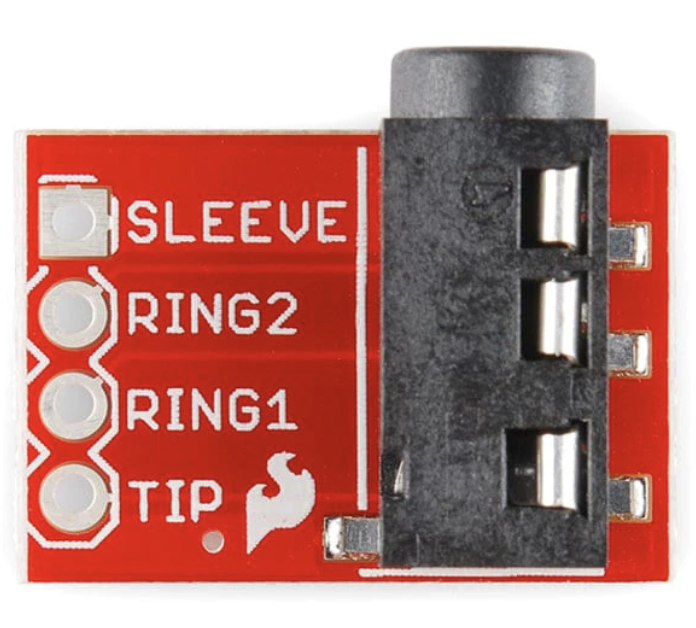
Pin Configuration and Descriptions
Below is the pinout for a standard TRRS connector following the CTIA standard (commonly used in modern devices):
| Pin Name | Position on Connector | Function |
|---|---|---|
| Tip | First (closest to the tip) | Left audio channel |
| Ring 1 | Second | Right audio channel |
| Ring 2 | Third | Microphone input |
| Sleeve | Fourth (closest to the cable) | Ground |
For the OMTP standard, the positions of the microphone and ground are swapped:
- Ring 2: Ground
- Sleeve: Microphone input
Usage Instructions
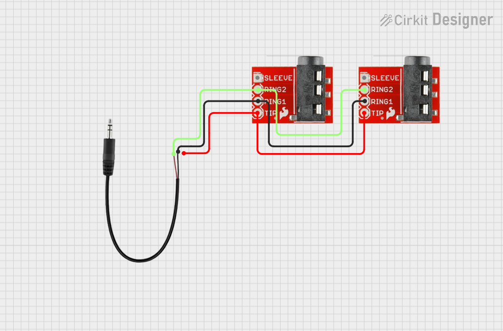
How to Use the TRRS Connector in a Circuit
- Identify the Standard: Determine whether your device uses the CTIA or OMTP standard. This is crucial for proper functionality.
- Connect the Pins:
- Use a TRRS breakout board or adapter for easy access to individual pins.
- Ensure the Tip and Rings are connected to the appropriate audio channels and microphone input.
- Connect the Sleeve to the ground of your circuit.
- Soldering Tips:
- Use a fine-tipped soldering iron for precise connections.
- Avoid overheating the connector to prevent damage to the plastic insulation.
Important Considerations and Best Practices
- Standard Compatibility: If your device uses a different standard (e.g., CTIA vs. OMTP), use an adapter to ensure proper pin alignment.
- Signal Interference: Use shielded cables to minimize noise and interference, especially for microphone signals.
- Testing Connections: Use a multimeter to verify continuity between the TRRS connector and your circuit before powering it on.
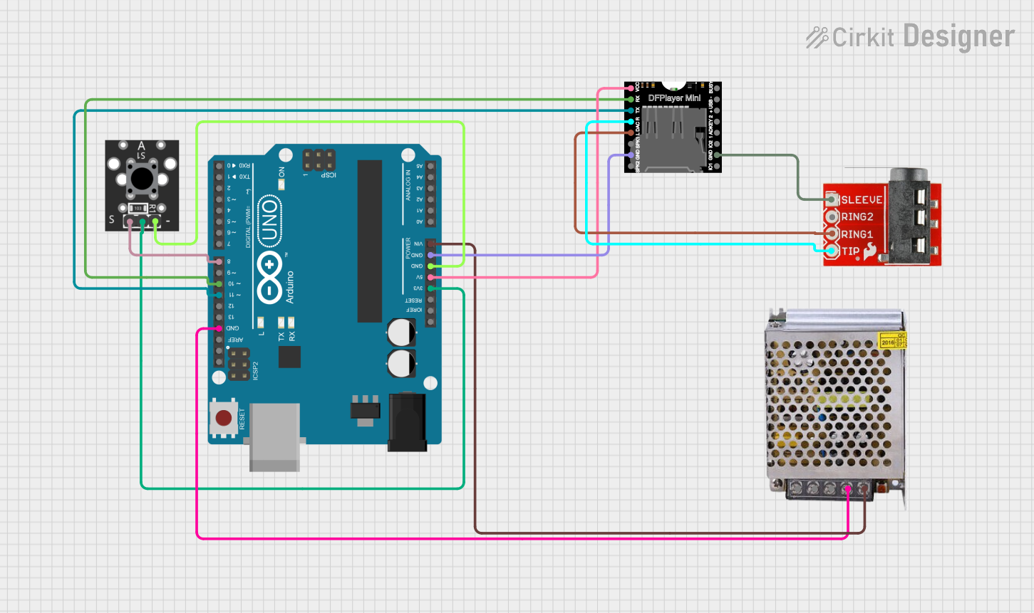
Example: Connecting a TRRS Microphone to an Arduino UNO
To interface a TRRS microphone with an Arduino UNO, you can use a TRRS breakout board. Below is an example code to read the microphone input:
// Example code to read analog input from a TRRS microphone connected to Arduino UNO
// Ensure the microphone pin is connected to an analog input pin (e.g., A0).

const int micPin = A0; // Microphone connected to analog pin A0
int micValue = 0;      // Variable to store microphone reading

void setup() {
  Serial.begin(9600); // Initialize serial communication at 9600 baud
}

void loop() {
  micValue = analogRead(micPin); // Read the microphone signal
  Serial.println(micValue);     // Print the value to the Serial Monitor
  delay(100);                   // Small delay for readability
}
Note: Use a capacitor and resistor in the circuit to filter and bias the microphone signal for better readings.
Troubleshooting and FAQs
Common Issues
No Audio or Microphone Signal:
- Cause: Incorrect standard (CTIA vs. OMTP) or misaligned connections.
- Solution: Verify the pinout and use an adapter if necessary.
Static or Noise in Audio:
- Cause: Poor shielding or loose connections.
- Solution: Use shielded cables and ensure all connections are secure.
Microphone Not Detected:
- Cause: Insufficient bias voltage for the microphone.
- Solution: Add a pull-up resistor or biasing circuit as required.
FAQs
Q: Can I use a TRRS connector for video signals?
- A: Yes, some TRRS connectors are used for composite video signals in addition to audio. Check the device's specifications for compatibility.
Q: How do I differentiate between CTIA and OMTP standards?
- A: Use a multimeter to check the continuity of the microphone and ground pins. Alternatively, consult the device's manual or use an adapter.
Q: Can I connect a TRRS headset to a PC with separate audio and mic jacks?
- A: Yes, but you will need a TRRS to dual 3.5mm adapter to split the audio and microphone signals.
By following this documentation, you can effectively use and troubleshoot TRRS connectors in your projects.