Cirkit Designer Logo
Cirkit Designer
Your all-in-one circuit design IDE
Home / 
Component Documentation

How to Use Coreless Motor Clock: Examples, Pinouts, and Specs

Image of Coreless Motor Clock
Cirkit Designer LogoDesign with Coreless Motor Clock in Cirkit Designer

Introduction

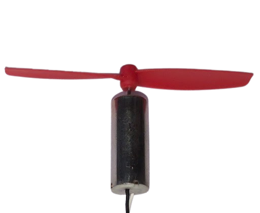
A coreless motor clock is a precision timekeeping device that utilizes a coreless DC motor to drive the clock mechanism. Unlike traditional motors with iron cores, coreless motors have a rotor that is not surrounded by an iron core, which reduces inertia and enables more precise control. This makes coreless motor clocks highly accurate and reliable for applications where precise timekeeping is essential, such as in wall clocks, wristwatches, and timing devices in various electronics.

Explore Projects Built with Coreless Motor Clock

Use Cirkit Designer to design, explore, and prototype these projects online. Some projects support real-time simulation. Click "Open Project" to start designing instantly!
ESP32 and DRV8833-Based Battery-Powered Motor Control System with MPU6050 Integration
Image of KSH: A project utilizing Coreless Motor Clock in a practical application
This circuit is a motor control system that uses an ESP32 microcontroller to control four coreless motors via two DRV8833 motor driver ICs. The ESP32 receives input from an MPU6050 accelerometer/gyroscope sensor and uses this data to drive the motors, powered by a 3.7V LiPo battery.
Cirkit Designer LogoOpen Project in Cirkit Designer
Dual Motor Control Circuit with LED Indicator and Adjustable Speed
Image of Simple Drone: A project utilizing Coreless Motor Clock in a practical application
This circuit is designed to control the speed and direction of coreless motors using MOSFETs, with a potentiometer providing adjustable speed control for one direction. A rocker switch enables power control, and a red LED serves as a power indicator. Diodes are included for motor back-EMF protection.
Cirkit Designer LogoOpen Project in Cirkit Designer
Coreless Motor Clock with Adjustable Speed Control using IRFZ44N MOSFET
Image of coreless pjt: A project utilizing Coreless Motor Clock in a practical application
This circuit controls the speed of a coreless motor using a trimmer potentiometer and an IRFZ44N MOSFET. The potentiometer adjusts the gate voltage of the MOSFET, which in turn regulates the current flowing through the motor, powered by a DC power source.
Cirkit Designer LogoOpen Project in Cirkit Designer
Arduino Pro Mini and HC-05 Bluetooth Controlled Coreless Motor Clock with MPU-6050 Feedback
Image of drone: A project utilizing Coreless Motor Clock in a practical application
This is a motion-controlled device with wireless capabilities, powered by a LiPo battery with voltage regulation. It uses an Arduino Pro Mini to process MPU-6050 sensor data and control coreless motors via MOSFETs, interfacing with an external device through an HC-05 Bluetooth module.
Cirkit Designer LogoOpen Project in Cirkit Designer

Explore Projects Built with Coreless Motor Clock

Use Cirkit Designer to design, explore, and prototype these projects online. Some projects support real-time simulation. Click "Open Project" to start designing instantly!
Image of KSH: A project utilizing Coreless Motor Clock in a practical application
ESP32 and DRV8833-Based Battery-Powered Motor Control System with MPU6050 Integration
This circuit is a motor control system that uses an ESP32 microcontroller to control four coreless motors via two DRV8833 motor driver ICs. The ESP32 receives input from an MPU6050 accelerometer/gyroscope sensor and uses this data to drive the motors, powered by a 3.7V LiPo battery.
Cirkit Designer LogoOpen Project in Cirkit Designer
Image of Simple Drone: A project utilizing Coreless Motor Clock in a practical application
Dual Motor Control Circuit with LED Indicator and Adjustable Speed
This circuit is designed to control the speed and direction of coreless motors using MOSFETs, with a potentiometer providing adjustable speed control for one direction. A rocker switch enables power control, and a red LED serves as a power indicator. Diodes are included for motor back-EMF protection.
Cirkit Designer LogoOpen Project in Cirkit Designer
Image of coreless pjt: A project utilizing Coreless Motor Clock in a practical application
Coreless Motor Clock with Adjustable Speed Control using IRFZ44N MOSFET
This circuit controls the speed of a coreless motor using a trimmer potentiometer and an IRFZ44N MOSFET. The potentiometer adjusts the gate voltage of the MOSFET, which in turn regulates the current flowing through the motor, powered by a DC power source.
Cirkit Designer LogoOpen Project in Cirkit Designer
Image of drone: A project utilizing Coreless Motor Clock in a practical application
Arduino Pro Mini and HC-05 Bluetooth Controlled Coreless Motor Clock with MPU-6050 Feedback
This is a motion-controlled device with wireless capabilities, powered by a LiPo battery with voltage regulation. It uses an Arduino Pro Mini to process MPU-6050 sensor data and control coreless motors via MOSFETs, interfacing with an external device through an HC-05 Bluetooth module.
Cirkit Designer LogoOpen Project in Cirkit Designer

Common Applications and Use Cases

  • Wall clocks
  • Wristwatches
  • Timing mechanisms in electronic devices
  • Precision instrumentation

Technical Specifications

Key Technical Details

Specification Value Description
Operating Voltage X - Y V The range of voltages the motor can operate at safely.
Current Rating Z mA The maximum current the motor can draw under load.
Power Rating W mW The power consumption of the motor.
Timekeeping Accuracy ±A ppm The precision of timekeeping, typically in parts per million.
Operating Temperature B - C °C The range of ambient temperatures within which the motor operates reliably.

Pin Configuration and Descriptions

Pin Number Name Description
1 VCC Connect to the positive voltage supply.
2 GND Connect to the ground.
3 TIME_ADJ Input for time adjustment.
4 PULSE_OUT Output pulse for clock mechanism.

Usage Instructions

How to Use the Component in a Circuit

  1. Power Supply Connection: Connect the VCC pin to a power supply within the specified operating voltage range and the GND pin to the ground.

  2. Time Adjustment: The TIME_ADJ pin can be used to fine-tune the timekeeping of the clock. This can be done through a variable resistor or a digital signal that adjusts the motor speed.

  3. Clock Mechanism Drive: Connect the PULSE_OUT pin to the clock mechanism. This pin outputs a pulse that advances the clock by one increment, typically one second.

Important Considerations and Best Practices

  • Ensure that the power supply does not exceed the recommended voltage range to prevent damage to the motor.
  • Avoid placing the clock in environments that exceed the operating temperature range.
  • For precise time adjustment, use a high-quality variable resistor or a stable digital signal.
  • Keep magnetic materials away from the coreless motor to prevent interference with its operation.

Troubleshooting and FAQs

Common Issues Users Might Face

  • Clock is not keeping accurate time: Check the TIME_ADJ setting and adjust as necessary. Ensure the power supply is stable and within the specified range.
  • Motor does not start: Verify that the power connections are correct and that the voltage is within the specified range. Check for any obstructions in the clock mechanism.

Solutions and Tips for Troubleshooting

  • If the clock is running fast or slow, fine-tune the TIME_ADJ pin.
  • Ensure that all connections are secure and free from corrosion or damage.
  • Replace the power supply if it is not providing a consistent voltage.

FAQs

Q: Can the coreless motor clock run on battery power? A: Yes, as long as the battery voltage is within the operating voltage range.

Q: How long will the coreless motor last? A: Coreless motors have a long lifespan due to their low friction and wear, but the exact duration depends on usage conditions.

Q: Is it possible to replace the coreless motor if it fails? A: Yes, the motor can be replaced, but it requires some technical skill to ensure proper alignment and connection with the clock mechanism.

Example Arduino Code for Coreless Motor Clock

// Define the pins
const int pulseOutPin = 3; // PULSE_OUT connected to digital pin 3

void setup() {
  // Set the pulseOutPin as an output:
  pinMode(pulseOutPin, OUTPUT);
}

void loop() {
  // Send a pulse every second to advance the clock
  digitalWrite(pulseOutPin, HIGH);   // Turn on the pulse
  delay(10);                         // Wait for 10 milliseconds
  digitalWrite(pulseOutPin, LOW);    // Turn off the pulse
  delay(990);                        // Wait for the remainder of the second
}

Note: The above code assumes that a single pulse advances the clock by one second. Adjust the delay times if your clock mechanism requires a different pulse duration or frequency.