How to Use RpLIDAR: Examples, Pinouts, and Specs
Introduction
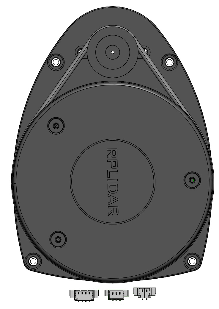
The RpLIDAR is a 2D laser scanner designed for mapping and navigation applications. It operates by emitting laser beams and detecting their reflections to measure distances, enabling the creation of detailed 2D maps of the surrounding environment. This component is widely used in robotics, autonomous vehicles, and other systems requiring spatial awareness and obstacle detection.
Explore Projects Built with RpLIDAR
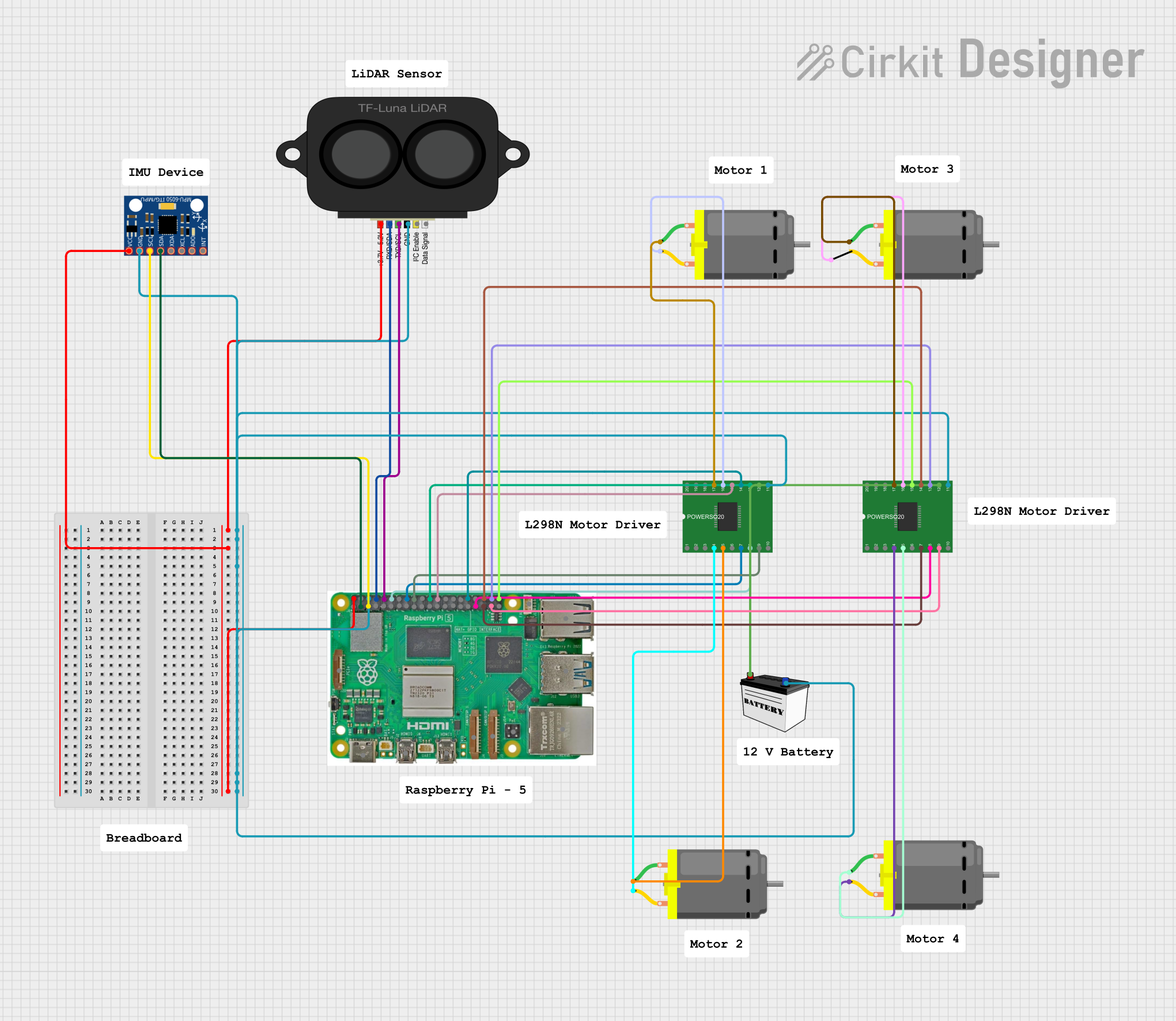
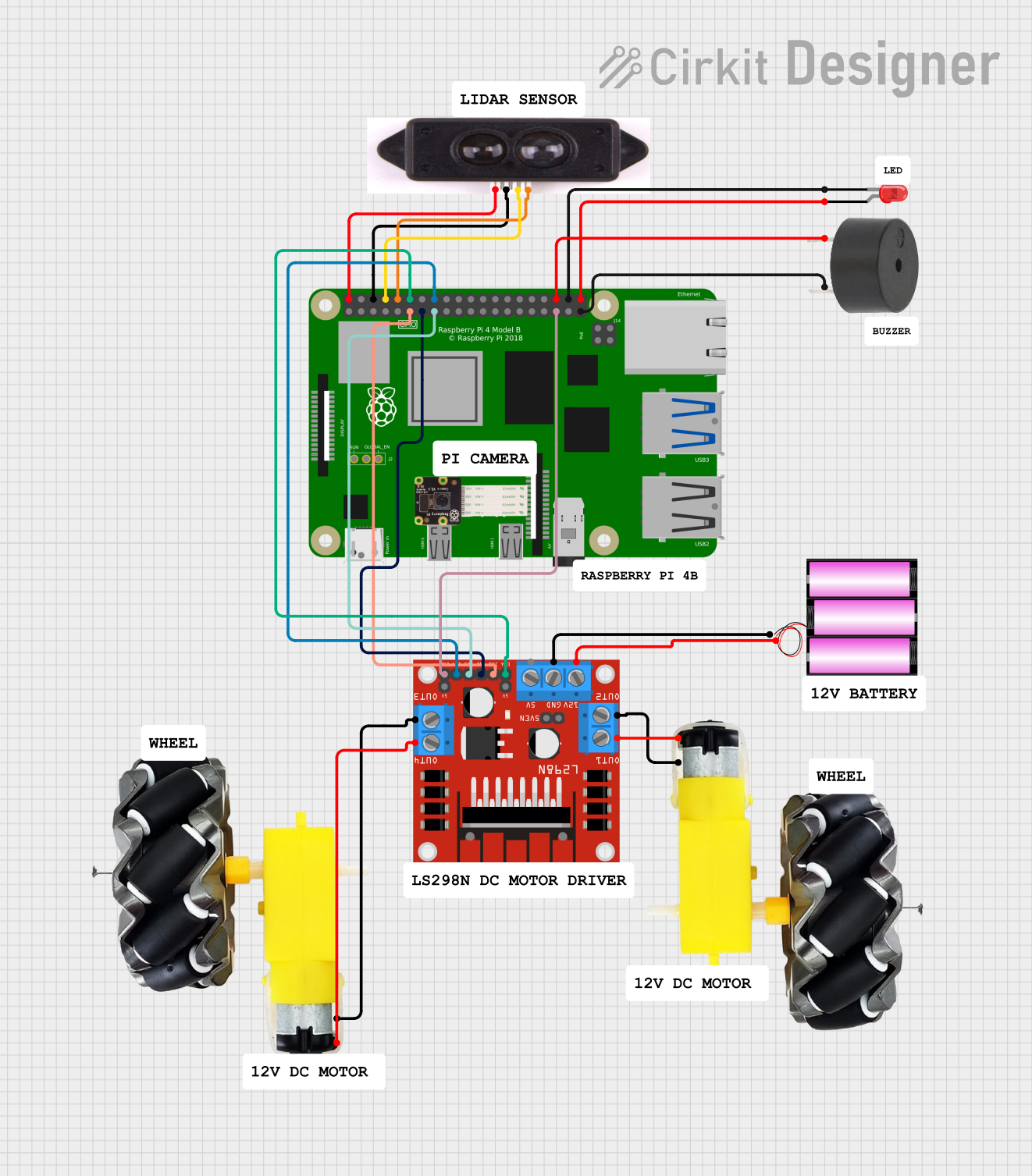
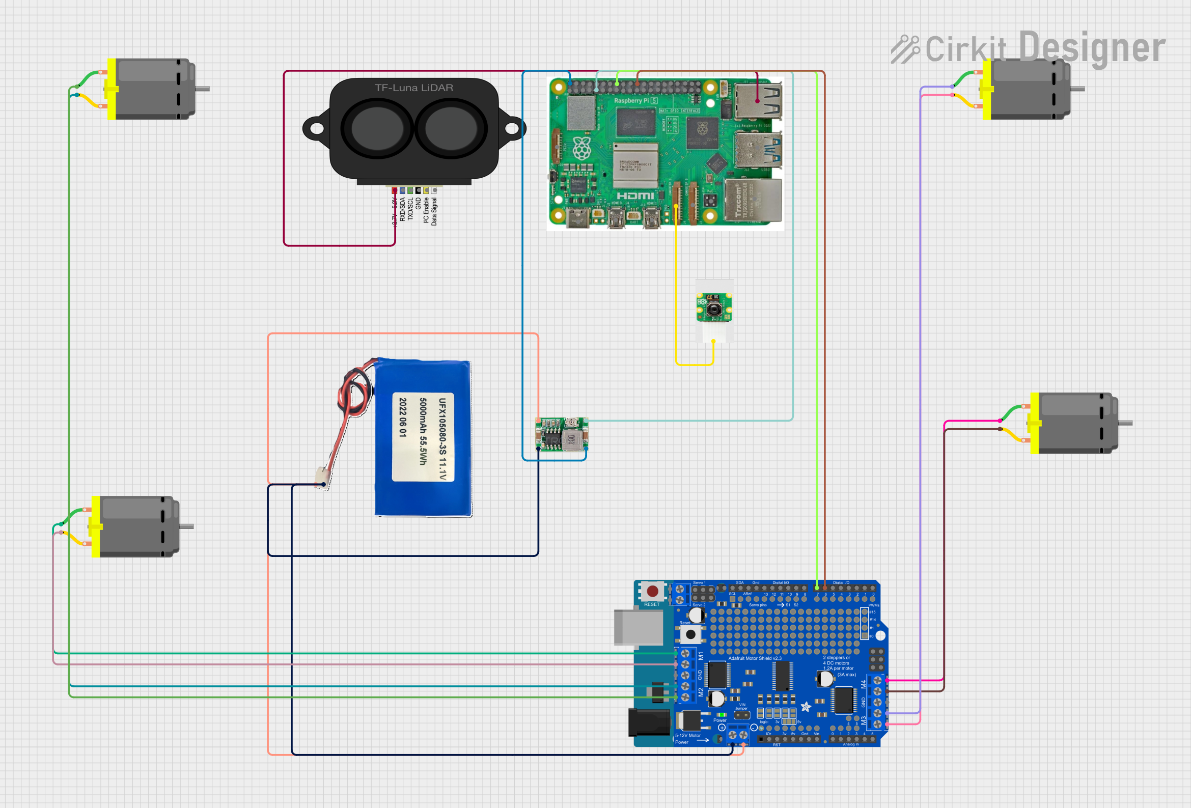
Explore Projects Built with RpLIDAR
Common Applications and Use Cases
- Robotics: Navigation, obstacle avoidance, and environment mapping.
- Autonomous Vehicles: Real-time spatial awareness and path planning.
- Industrial Automation: Object detection and area monitoring.
- Research and Development: SLAM (Simultaneous Localization and Mapping) experiments.
- Smart Devices: Indoor mapping and localization.
Technical Specifications
The RpLIDAR is available in various models (e.g., A1, A2, A3, S1), but the following specifications are typical for the series:
| Parameter | Specification |
|---|---|
| Measurement Range | 0.15 m to 12 m (varies by model) |
| Angular Resolution | 0.5° to 1° |
| Scanning Frequency | 5 Hz to 15 Hz (adjustable) |
| Distance Accuracy | ±1% (within 1-6 m range) |
| Laser Wavelength | 785 nm (infrared) |
| Laser Safety Class | Class 1 (eye-safe) |
| Communication Interface | UART (3.3V TTL) or USB |
| Operating Voltage | 5V DC |
| Power Consumption | 2W to 5W (depending on model and usage) |
| Dimensions | ~70 mm diameter, ~40 mm height |
| Weight | ~190 g |
Pin Configuration and Descriptions
The RpLIDAR typically uses a 4-pin interface for communication and power. Below is the pinout:
| Pin | Name | Description |
|---|---|---|
| 1 | VCC | Power input (5V DC) |
| 2 | GND | Ground |
| 3 | TX (UART) | Transmit data (3.3V TTL) |
| 4 | RX (UART) | Receive data (3.3V TTL) |
For USB-based models, the communication is handled via a USB interface, and no additional pin configuration is required.
Usage Instructions
How to Use the RpLIDAR in a Circuit
- Power Supply: Connect the VCC pin to a stable 5V DC power source and the GND pin to the ground.
- Communication: Use the TX and RX pins to interface with a microcontroller or computer via UART. For USB models, connect the device directly to a USB port.
- Mounting: Secure the RpLIDAR on a stable platform to minimize vibrations during operation.
- Data Processing: Use the manufacturer's SDK or libraries to process the data and generate 2D maps.
Important Considerations and Best Practices
- Laser Safety: Although the RpLIDAR uses a Class 1 laser, avoid staring directly into the laser aperture.
- Environment: Ensure the operating environment is free of excessive dust, smoke, or reflective surfaces, as these can interfere with measurements.
- Power Supply: Use a regulated power source to avoid voltage fluctuations that may affect performance.
- Firmware and Drivers: Install the latest firmware and drivers provided by the manufacturer for optimal performance.
- Calibration: Periodically calibrate the device to maintain accuracy.
Example: Connecting RpLIDAR to Arduino UNO
Below is an example of how to connect and use the RpLIDAR with an Arduino UNO:
Wiring
- VCC: Connect to the Arduino's 5V pin.
- GND: Connect to the Arduino's GND pin.
- TX: Connect to the Arduino's RX pin (digital pin 0).
- RX: Connect to the Arduino's TX pin (digital pin 1).
Code Example
#include <SoftwareSerial.h>

// Define RX and TX pins for SoftwareSerial
SoftwareSerial lidarSerial(10, 11); // RX = pin 10, TX = pin 11

void setup() {
  Serial.begin(9600); // Initialize Serial Monitor
  lidarSerial.begin(115200); // Initialize RpLIDAR communication

  Serial.println("RpLIDAR Test Initialized");
}

void loop() {
  if (lidarSerial.available()) {
    // Read data from RpLIDAR and send it to Serial Monitor
    char data = lidarSerial.read();
    Serial.print(data);
  }
}
Note: The above code assumes the use of a SoftwareSerial library to free up the Arduino's default UART pins. Adjust the baud rate and pins as needed for your specific setup.
Troubleshooting and FAQs
Common Issues and Solutions
No Data Output:
- Cause: Incorrect wiring or baud rate mismatch.
- Solution: Verify the connections and ensure the baud rate matches the RpLIDAR's default setting (typically 115200).
Inaccurate Measurements:
- Cause: Dust or dirt on the laser window.
- Solution: Clean the laser window with a soft, lint-free cloth.
Device Not Detected:
- Cause: Missing drivers or incorrect USB connection.
- Solution: Install the required drivers and ensure the USB cable is functional.
Interference in Readings:
- Cause: Reflective or transparent surfaces in the environment.
- Solution: Avoid placing the RpLIDAR near such surfaces or use a model with better interference handling.
FAQs
Q: Can the RpLIDAR be used outdoors?
- A: While it can operate outdoors, direct sunlight and extreme weather conditions may affect performance. Use a protective enclosure for outdoor applications.
Q: How do I update the firmware?
- A: Use the manufacturer's firmware update tool, typically available on their website, and follow the provided instructions.
Q: Is the RpLIDAR compatible with Raspberry Pi?
- A: Yes, the RpLIDAR can be interfaced with Raspberry Pi using the UART or USB interface. Libraries like
rplidar_rosorrplidar_sdkare available for integration.
- A: Yes, the RpLIDAR can be interfaced with Raspberry Pi using the UART or USB interface. Libraries like
Q: What is the lifespan of the RpLIDAR?
- A: The lifespan depends on usage but is typically rated for over 10,000 hours of operation.
By following this documentation, you can effectively integrate and utilize the RpLIDAR in your projects.