
How to Use LilyPad Accelerometer ADXL335: Examples, Pinouts, and Specs
 Design with LilyPad Accelerometer ADXL335 in Cirkit Designer
Introduction
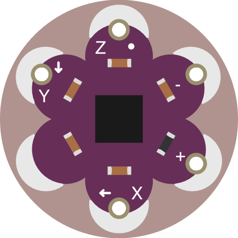
The LilyPad Accelerometer ADXL335 (Manufacturer Part ID: DEV-09267) is a compact, low-power accelerometer designed by SparkFun Electronics. It measures acceleration in three axes (X, Y, Z) and is ideal for wearable electronics and motion-sensing applications. Its circular, sewable design makes it perfect for e-textile projects, while its low power consumption ensures efficient operation in battery-powered systems.
Explore Projects Built with LilyPad Accelerometer ADXL335
 Open Project in Cirkit Designer
 Open Project in Cirkit Designer
 Open Project in Cirkit Designer
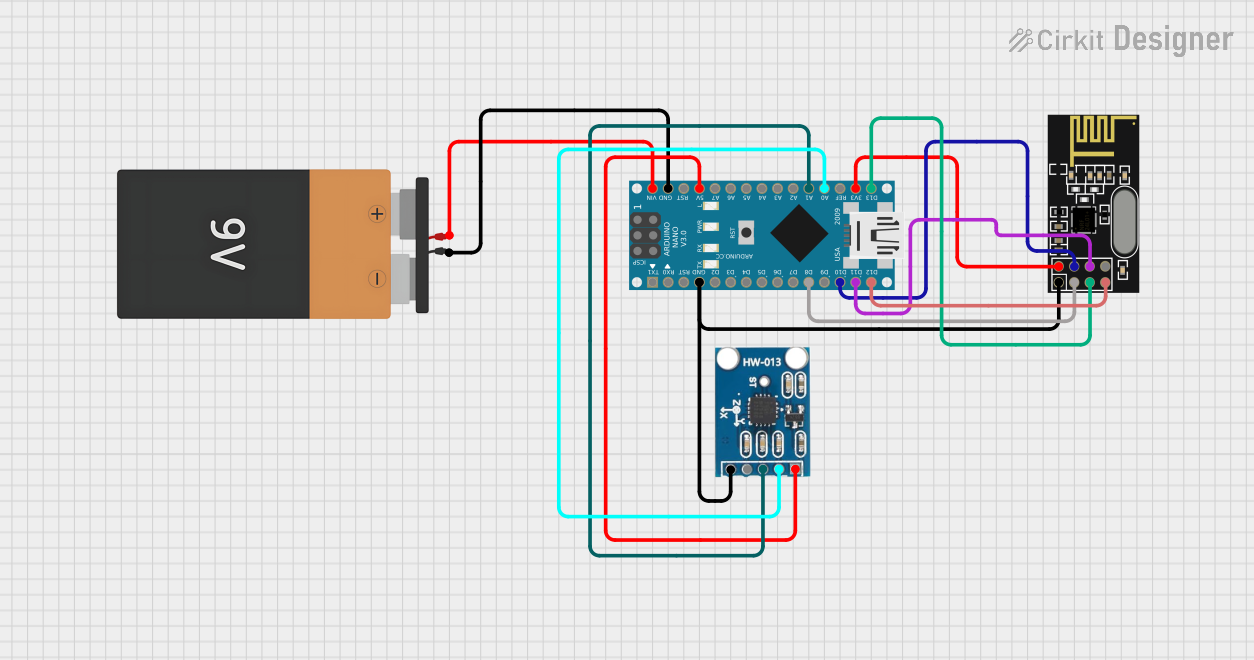 Open Project in Cirkit Designer
Explore Projects Built with LilyPad Accelerometer ADXL335
Open Project in Cirkit DesignerOpen Project in Cirkit DesignerOpen Project in Cirkit DesignerOpen Project in Cirkit DesignerCommon Applications
- Wearable electronics and e-textiles
- Motion detection and orientation sensing
- Gaming controllers and interactive devices
- Robotics and gesture recognition
- Fitness and health monitoring systems
Technical Specifications
The following table outlines the key technical details of the LilyPad Accelerometer ADXL335:
| Parameter | Value |
|---|---|
| Supply Voltage (Vcc) | 1.8V to 3.6V |
| Typical Operating Voltage | 3.3V |
| Current Consumption | 350 µA (typical) |
| Measurement Range | ±3g |
| Sensitivity | 300 mV/g (at 3.3V supply) |
| Axes | 3 (X, Y, Z) |
| Output Type | Analog |
| Operating Temperature | -40°C to +85°C |
| Dimensions | 20mm diameter |
Pin Configuration
The LilyPad Accelerometer ADXL335 has six sewable connection pads. The table below describes each pin:
| Pin Name | Description |
|---|---|
| VCC | Power supply input (1.8V to 3.6V, typically 3.3V). |
| GND | Ground connection. |
| X | Analog output for acceleration along the X-axis. |
| Y | Analog output for acceleration along the Y-axis. |
| Z | Analog output for acceleration along the Z-axis. |
| ST | Self-test pin (used for testing the accelerometer; leave unconnected in normal use). |
Usage Instructions
Connecting the LilyPad Accelerometer ADXL335
- Power Supply: Connect the
VCCpin to a 3.3V power source and theGNDpin to ground. - Analog Outputs: Connect the
X,Y, andZpins to the analog input pins of a microcontroller (e.g., Arduino UNO). - Self-Test Pin: Leave the
STpin unconnected unless performing a self-test.
Example Circuit with Arduino UNO
Below is an example of how to connect the LilyPad Accelerometer ADXL335 to an Arduino UNO:
| LilyPad ADXL335 Pin | Arduino UNO Pin |
|---|---|
| VCC | 3.3V |
| GND | GND |
| X | A0 |
| Y | A1 |
| Z | A2 |
Sample Arduino Code
The following Arduino sketch reads the analog values from the accelerometer and prints the acceleration data to the Serial Monitor.
// LilyPad Accelerometer ADXL335 Example Code
// Reads X, Y, Z axis data and prints it to the Serial Monitor

// Define the analog pins connected to the accelerometer
const int xPin = A0; // X-axis output
const int yPin = A1; // Y-axis output
const int zPin = A2; // Z-axis output

void setup() {
  Serial.begin(9600); // Initialize serial communication at 9600 baud
}

void loop() {
  // Read analog values from the accelerometer
  int xValue = analogRead(xPin);
  int yValue = analogRead(yPin);
  int zValue = analogRead(zPin);

  // Convert the analog values to voltage (assuming 3.3V reference)
  float xVoltage = xValue * (3.3 / 1023.0);
  float yVoltage = yValue * (3.3 / 1023.0);
  float zVoltage = zValue * (3.3 / 1023.0);

  // Print the voltage values to the Serial Monitor
  Serial.print("X Voltage: ");
  Serial.print(xVoltage);
  Serial.print(" V, Y Voltage: ");
  Serial.print(yVoltage);
  Serial.print(" V, Z Voltage: ");
  Serial.print(zVoltage);
  Serial.println(" V");

  delay(500); // Wait for 500ms before the next reading
}
Important Considerations
- Power Supply: Ensure the accelerometer is powered with a voltage between 1.8V and 3.6V. Exceeding this range may damage the component.
- Analog Reference Voltage: If using a microcontroller with a 5V analog reference (e.g., Arduino UNO), consider using a voltage divider or level shifter to avoid inaccurate readings.
- Noise Filtering: For smoother readings, consider adding capacitors between the output pins (X, Y, Z) and ground to filter noise.
Troubleshooting and FAQs
Common Issues and Solutions
No Output or Incorrect Readings:
- Verify that the
VCCandGNDpins are properly connected. - Ensure the supply voltage is within the specified range (1.8V to 3.6V).
- Check the connections to the analog input pins of the microcontroller.
- Verify that the
Fluctuating or Noisy Readings:
- Add decoupling capacitors (e.g., 0.1 µF) between the output pins (X, Y, Z) and ground.
- Ensure the accelerometer is securely mounted to avoid mechanical vibrations.
Self-Test Pin Misuse:
- The
STpin is only for testing purposes. Leave it unconnected during normal operation.
- The
FAQs
Q: Can I use the LilyPad Accelerometer ADXL335 with a 5V microcontroller?
A: Yes, but you must ensure the analog reference voltage of the microcontroller matches the accelerometer's output range. Use a voltage divider or level shifter if necessary.
Q: How do I interpret the output values?
A: The analog outputs correspond to the acceleration along each axis. At rest, the outputs should be approximately half the supply voltage (e.g., ~1.65V for a 3.3V supply).
Q: Can I use this accelerometer for free-fall detection?
A: Yes, the ADXL335 can detect free-fall events by monitoring the output voltages for near-zero values on all axes.
Q: Is the LilyPad Accelerometer ADXL335 waterproof?
A: No, the component is not waterproof. Protect it from moisture in wearable applications.
By following this documentation, you can effectively integrate the LilyPad Accelerometer ADXL335 into your projects for reliable motion sensing and orientation detection.