How to Use PLC: Examples, Pinouts, and Specs
Introduction
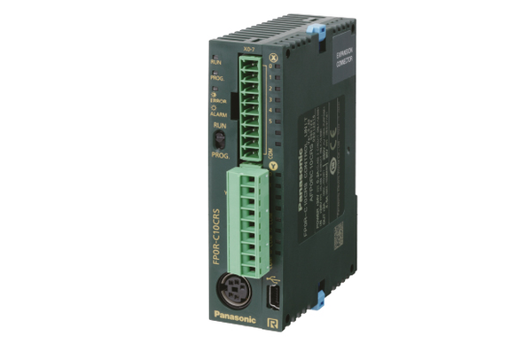
A Programmable Logic Controller (PLC) is an industrial digital computer designed for the control and automation of manufacturing processes or robotic devices. Panasonic's PLCs are known for their reliability, flexibility, and ease of integration into various industrial environments. They are widely used in applications such as assembly lines, robotic devices, and any system requiring high reliability and ease of programming.
Explore Projects Built with PLC

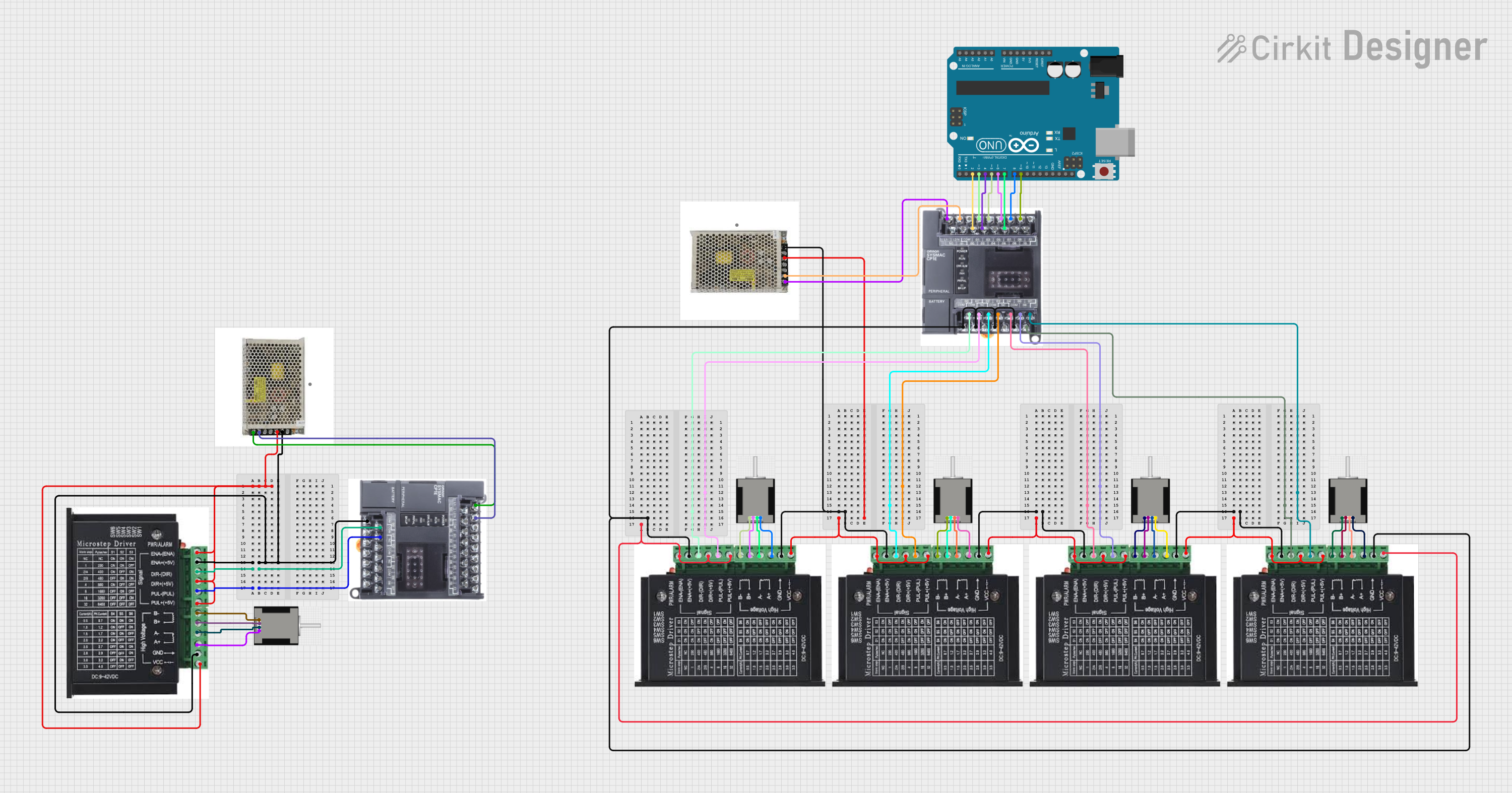


Explore Projects Built with PLC
Technical Specifications
Key Technical Details
| Specification | Value |
|---|---|
| Manufacturer | Panasonic |
| Part ID | PLC |
| Operating Voltage | 24V DC |
| Input Voltage Range | 20.4V to 28.8V DC |
| Power Consumption | 5W |
| Operating Temperature | -10°C to 55°C |
| Storage Temperature | -20°C to 70°C |
| Humidity | 10% to 90% (non-condensing) |
| Communication Ports | RS232, RS485, Ethernet |
| Digital Inputs | 16 |
| Digital Outputs | 16 |
| Analog Inputs | 4 |
| Analog Outputs | 2 |
Pin Configuration and Descriptions
Digital Inputs
| Pin Number | Description |
|---|---|
| 1 | Digital Input 1 |
| 2 | Digital Input 2 |
| 3 | Digital Input 3 |
| 4 | Digital Input 4 |
| 5 | Digital Input 5 |
| 6 | Digital Input 6 |
| 7 | Digital Input 7 |
| 8 | Digital Input 8 |
| 9 | Digital Input 9 |
| 10 | Digital Input 10 |
| 11 | Digital Input 11 |
| 12 | Digital Input 12 |
| 13 | Digital Input 13 |
| 14 | Digital Input 14 |
| 15 | Digital Input 15 |
| 16 | Digital Input 16 |
Digital Outputs
| Pin Number | Description |
|---|---|
| 1 | Digital Output 1 |
| 2 | Digital Output 2 |
| 3 | Digital Output 3 |
| 4 | Digital Output 4 |
| 5 | Digital Output 5 |
| 6 | Digital Output 6 |
| 7 | Digital Output 7 |
| 8 | Digital Output 8 |
| 9 | Digital Output 9 |
| 10 | Digital Output 10 |
| 11 | Digital Output 11 |
| 12 | Digital Output 12 |
| 13 | Digital Output 13 |
| 14 | Digital Output 14 |
| 15 | Digital Output 15 |
| 16 | Digital Output 16 |
Usage Instructions
How to Use the Component in a Circuit
- Power Supply: Connect the PLC to a 24V DC power supply. Ensure the power supply can provide sufficient current for the PLC and any connected devices.
- Digital Inputs: Connect sensors or switches to the digital input pins. Ensure the input voltage levels are within the specified range.
- Digital Outputs: Connect actuators, relays, or other devices to the digital output pins. Ensure the output current and voltage ratings are not exceeded.
- Analog Inputs/Outputs: Connect analog sensors or devices to the analog input/output pins. Ensure proper signal conditioning if necessary.
- Communication Ports: Use RS232, RS485, or Ethernet ports for communication with other devices or systems. Configure the communication settings as required.
Important Considerations and Best Practices
- Grounding: Ensure proper grounding to avoid electrical noise and interference.
- Shielding: Use shielded cables for analog signals to prevent noise interference.
- Surge Protection: Implement surge protection devices to protect the PLC from voltage spikes.
- Regular Maintenance: Perform regular maintenance checks to ensure the PLC and connected devices are functioning correctly.
Troubleshooting and FAQs
Common Issues Users Might Face
PLC Not Powering On:
- Solution: Check the power supply connections and ensure the voltage is within the specified range.
Digital Inputs Not Responding:
- Solution: Verify the input connections and ensure the sensors or switches are functioning correctly.
Digital Outputs Not Activating:
- Solution: Check the output connections and ensure the connected devices are within the output current and voltage ratings.
Communication Issues:
- Solution: Verify the communication port settings and ensure the cables are properly connected.
Solutions and Tips for Troubleshooting
- Check Connections: Ensure all connections are secure and correctly wired.
- Verify Power Supply: Ensure the power supply is providing the correct voltage and current.
- Inspect for Damage: Check for any physical damage to the PLC or connected devices.
- Consult the Manual: Refer to the manufacturer's manual for detailed troubleshooting steps and technical support.
Example Code for Arduino UNO Integration
While PLCs are typically used in industrial settings, they can also be integrated with microcontrollers like the Arduino UNO for educational or prototyping purposes. Below is an example code snippet for reading a digital input from a PLC and controlling an LED based on the input state.
// Define the digital input pin from the PLC
const int plcInputPin = 2;
// Define the LED output pin
const int ledPin = 13;

void setup() {
  // Initialize the digital input pin as an input
  pinMode(plcInputPin, INPUT);
  // Initialize the LED pin as an output
  pinMode(ledPin, OUTPUT);
  // Start the serial communication for debugging
  Serial.begin(9600);
}

void loop() {
  // Read the state of the PLC input pin
  int plcInputState = digitalRead(plcInputPin);

  // Print the input state to the serial monitor
  Serial.print("PLC Input State: ");
  Serial.println(plcInputState);

  // Control the LED based on the PLC input state
  if (plcInputState == HIGH) {
    // Turn the LED on if the input is HIGH
    digitalWrite(ledPin, HIGH);
  } else {
    // Turn the LED off if the input is LOW
    digitalWrite(ledPin, LOW);
  }

  // Add a small delay to avoid flooding the serial monitor
  delay(100);
}
This code reads the state of a digital input from the PLC and controls an LED on the Arduino UNO based on the input state. Ensure proper connections between the PLC and Arduino UNO, and adjust the pin numbers as needed.
This documentation provides a comprehensive overview of the Panasonic PLC, including technical specifications, usage instructions, troubleshooting tips, and example code for integration with an Arduino UNO. Whether you are a beginner or an experienced user, this guide aims to help you effectively utilize the PLC in your projects.