How to Use ILI9341: Examples, Pinouts, and Specs
Introduction
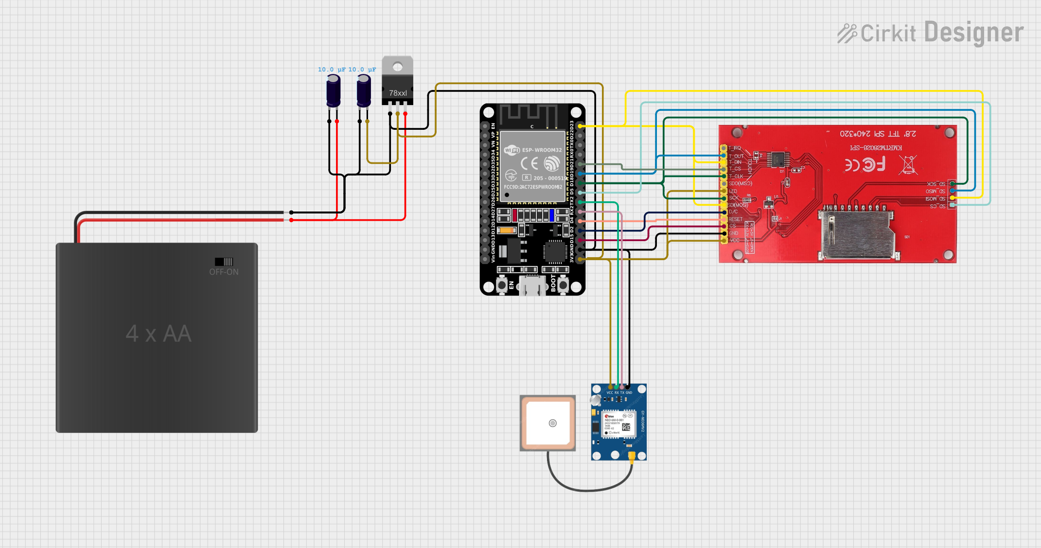
The ILI9341 is a TFT LCD display controller designed to drive 240x320 pixel displays with a 16-bit color depth. It is widely used in embedded systems for creating graphical user interfaces, displaying images, and rendering text. The controller supports communication via SPI (Serial Peripheral Interface) or parallel interfaces, making it versatile and compatible with a variety of microcontrollers.
Explore Projects Built with ILI9341
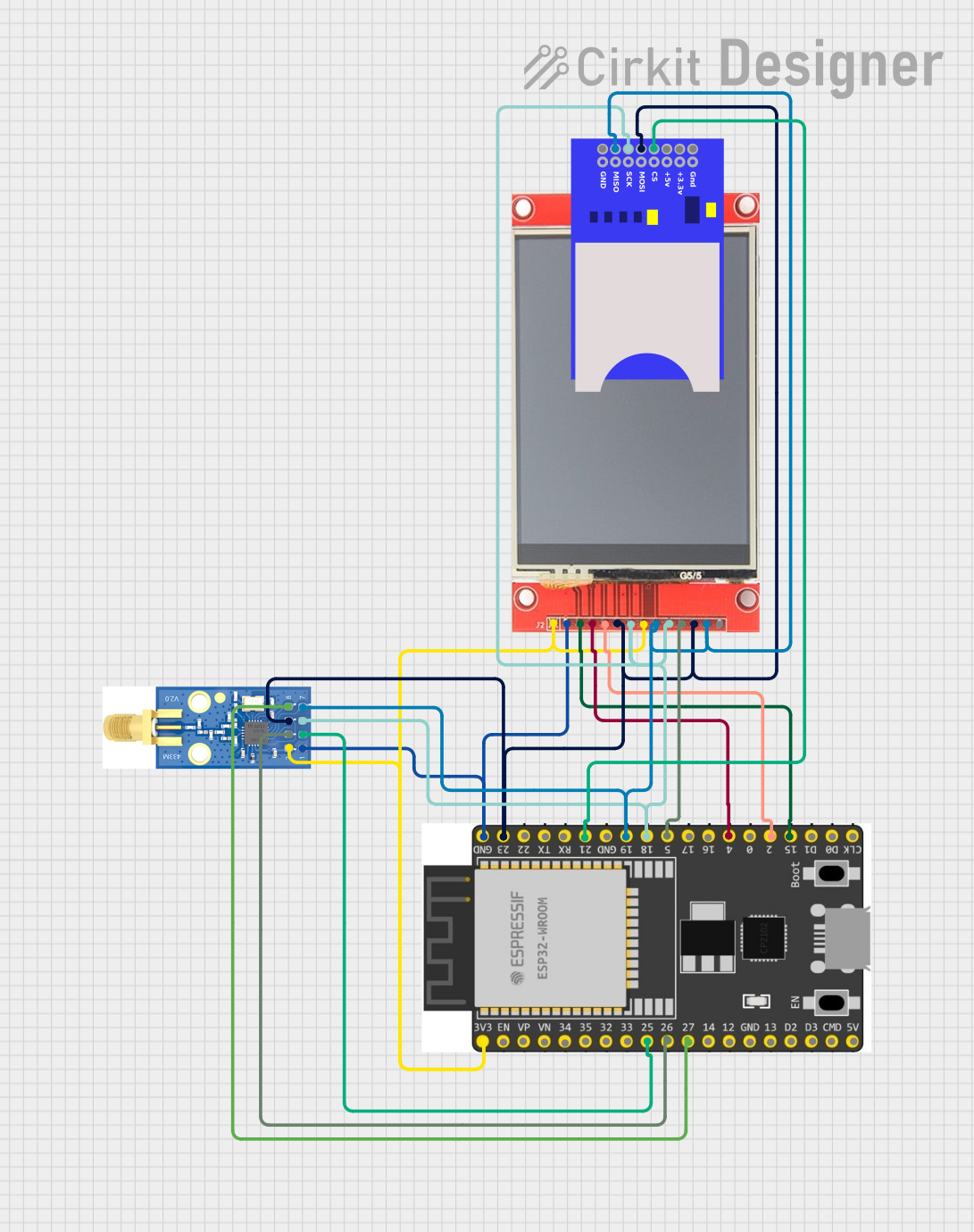
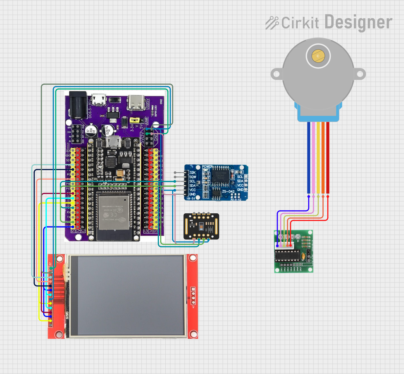
Explore Projects Built with ILI9341
Common Applications and Use Cases
- Graphical user interfaces for embedded systems
- Displaying sensor data in IoT devices
- Portable gaming consoles
- Industrial control panels
- Educational and hobbyist projects with microcontrollers like Arduino and Raspberry Pi
Technical Specifications
The ILI9341 controller is packed with features that make it suitable for high-quality graphical displays. Below are its key technical specifications:
| Specification | Details |
|---|---|
| Resolution | 240x320 pixels |
| Color Depth | 16-bit (65,536 colors) |
| Communication Interface | SPI (4-wire) or Parallel (8/16-bit) |
| Operating Voltage | 2.8V to 3.3V |
| Backlight Voltage | 3.0V to 3.3V |
| Maximum Clock Speed | 10 MHz (SPI mode) |
| Operating Temperature | -20°C to 70°C |
| Controller Dimensions | Varies based on display module |
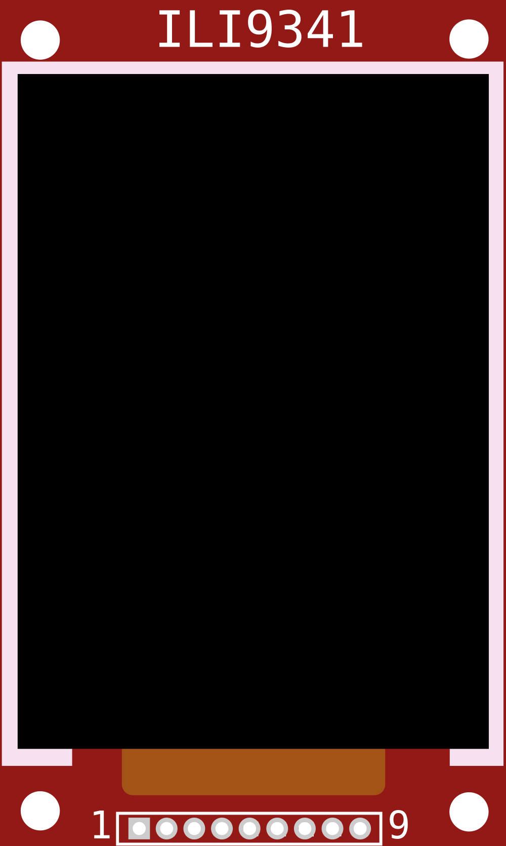
Pin Configuration and Descriptions
The ILI9341 is typically used with a TFT display module. Below is the pinout for a common SPI-based ILI9341 module:
| Pin Name | Description |
|---|---|
| VCC | Power supply input (3.3V recommended) |
| GND | Ground connection |
| CS | Chip Select (active low, used to enable communication with the display) |
| RESET | Reset pin (active low, used to reset the display controller) |
| DC (or RS) | Data/Command pin (used to distinguish between data and command instructions) |
| SDI (MOSI) | Serial Data Input (Master Out Slave In, used for SPI communication) |
| SCK | Serial Clock (used to synchronize SPI communication) |
| LED | Backlight control (connect to 3.3V or PWM for brightness control) |
| MISO | Serial Data Output (Master In Slave Out, optional for bidirectional SPI) |
Note: Some modules may have additional pins for touch functionality or parallel communication.
Usage Instructions
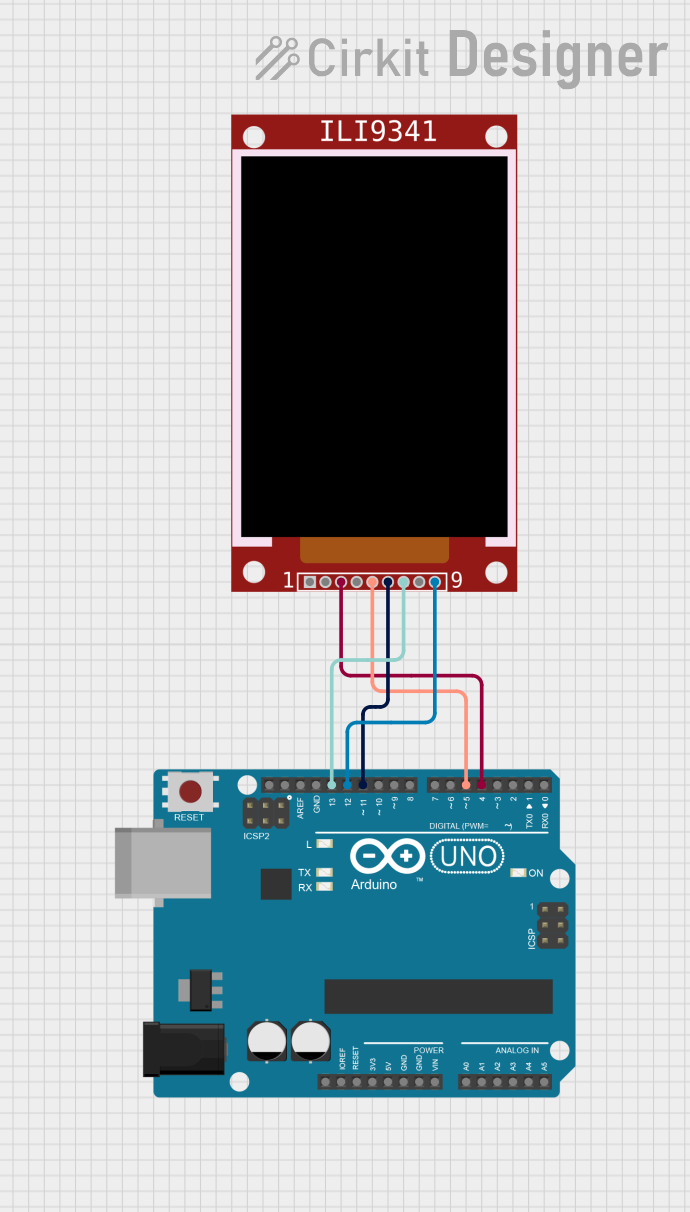
The ILI9341 can be easily integrated into a circuit using its SPI interface. Below are the steps to use the ILI9341 with an Arduino UNO:
Connecting the ILI9341 to Arduino UNO
- Connect the VCC pin of the ILI9341 module to the 3.3V pin on the Arduino.
- Connect the GND pin to the Arduino's GND.
- Connect the CS pin to Arduino pin 10 (or any other digital pin, configurable in code).
- Connect the RESET pin to Arduino pin 9.
- Connect the DC pin to Arduino pin 8.
- Connect the SDI (MOSI) pin to Arduino pin 11.
- Connect the SCK pin to Arduino pin 13.
- If the module has an LED pin, connect it to 3.3V or a PWM pin for brightness control.
Example Code for Arduino UNO
Below is an example of how to initialize and display graphics on the ILI9341 using the Adafruit GFX and Adafruit ILI9341 libraries:
#include <Adafruit_GFX.h>    // Core graphics library
#include <Adafruit_ILI9341.h> // ILI9341 driver library

// Define pin connections
#define TFT_CS   10  // Chip Select pin
#define TFT_RST  9   // Reset pin
#define TFT_DC   8   // Data/Command pin

// Create an instance of the ILI9341 display
Adafruit_ILI9341 tft = Adafruit_ILI9341(TFT_CS, TFT_DC, TFT_RST);

void setup() {
  // Initialize the display
  tft.begin();

  // Set rotation (0-3 for different orientations)
  tft.setRotation(1);

  // Fill the screen with a solid color
  tft.fillScreen(ILI9341_BLUE);

  // Draw a rectangle
  tft.fillRect(50, 50, 100, 100, ILI9341_RED);

  // Display text
  tft.setTextColor(ILI9341_WHITE);
  tft.setTextSize(2);
  tft.setCursor(10, 10);
  tft.print("Hello, ILI9341!");
}

void loop() {
  // Nothing to do here
}
Important Considerations and Best Practices
- Voltage Levels: Ensure that the ILI9341 module operates at 3.3V. If using a 5V microcontroller, use level shifters to avoid damaging the module.
- SPI Speed: The SPI clock speed should not exceed 10 MHz for reliable communication.
- Backlight Control: Use a PWM pin to control the brightness of the backlight for power efficiency.
- Library Compatibility: Use well-supported libraries like Adafruit GFX and Adafruit ILI9341 for easier integration and functionality.
Troubleshooting and FAQs
Common Issues and Solutions
Display Not Turning On:
- Check the power connections and ensure the module is receiving 3.3V.
- Verify that the backlight pin (LED) is connected to 3.3V or a PWM pin.
No Output on the Screen:
- Ensure the SPI connections (CS, DC, MOSI, SCK) are correctly wired.
- Verify that the correct pins are defined in the code.
Flickering or Unstable Display:
- Reduce the SPI clock speed in the library settings.
- Check for loose connections or poor soldering.
Incorrect Colors or Graphics:
- Ensure the color depth and rotation settings in the code match the display module.
- Verify that the library being used supports the ILI9341.
FAQs
Q: Can I use the ILI9341 with a 5V microcontroller?
A: Yes, but you must use level shifters to convert the 5V logic signals to 3.3V to avoid damaging the module.
Q: How do I control the brightness of the backlight?
A: Connect the LED pin to a PWM-capable pin on your microcontroller and use analogWrite() to adjust brightness.
Q: Can I use the ILI9341 in parallel mode?
A: Yes, the ILI9341 supports an 8-bit or 16-bit parallel interface, but it requires more pins and is less common in hobbyist projects.
Q: What is the maximum resolution supported by the ILI9341?
A: The ILI9341 supports a maximum resolution of 240x320 pixels.
By following this documentation, you should be able to successfully integrate and use the ILI9341 in your projects!