
How to Use connector 1 in 2 out: Examples, Pinouts, and Specs
 Design with connector 1 in 2 out in Cirkit Designer
Introduction
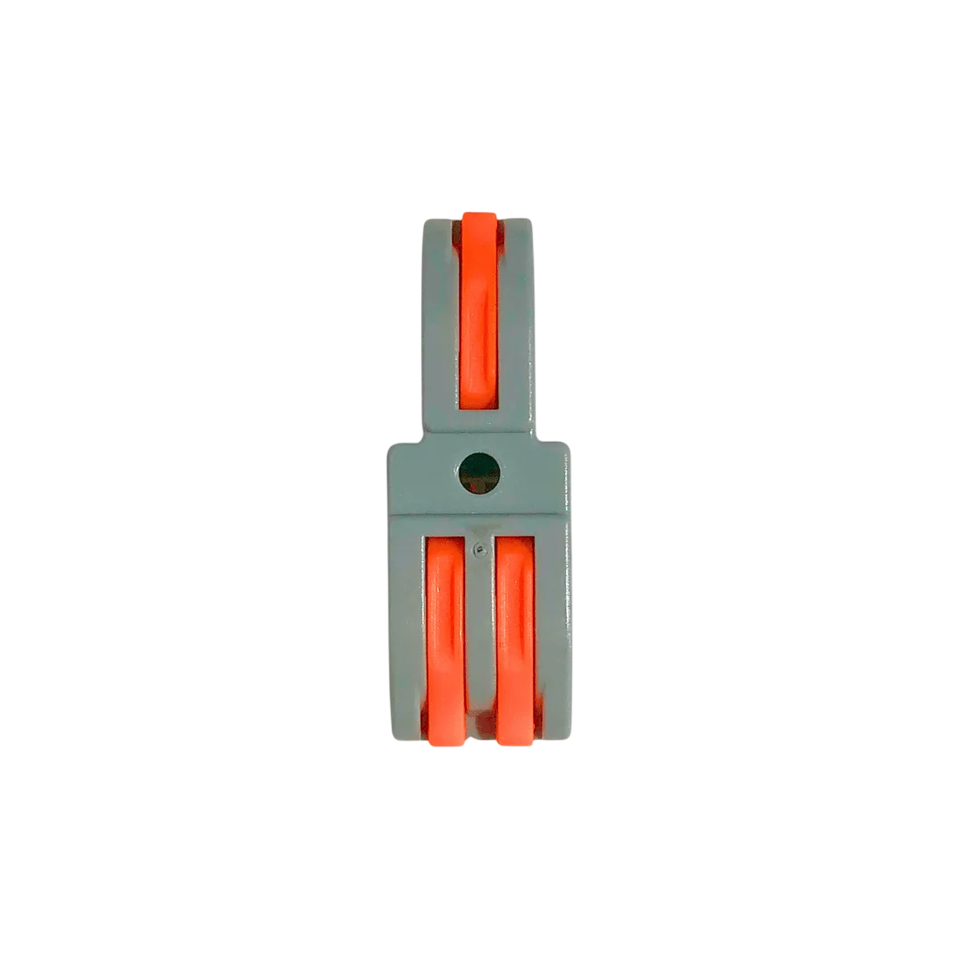
The Connector 1 In 2 Out is a versatile electronic component designed to split a single input signal into two output paths. It is commonly used in audio, video, and data transmission applications where signal distribution is required. This connector ensures that the input signal is evenly distributed to both outputs without significant loss or interference, making it ideal for use in home audio systems, data networks, and other signal-sharing setups.
Explore Projects Built with connector 1 in 2 out
 Open Project in Cirkit Designer
 Open Project in Cirkit Designer
 Open Project in Cirkit Designer
 Open Project in Cirkit Designer
Explore Projects Built with connector 1 in 2 out
Open Project in Cirkit DesignerOpen Project in Cirkit DesignerOpen Project in Cirkit DesignerOpen Project in Cirkit DesignerCommon Applications and Use Cases
- Audio Systems: Splitting a single audio source to feed two amplifiers or speakers.
- Video Distribution: Sending a video signal to two displays simultaneously.
- Data Transmission: Distributing a single data signal to two devices in low-speed communication systems.
- Testing and Prototyping: Splitting signals for simultaneous monitoring and analysis.
Technical Specifications
The Connector 1 In 2 Out is a passive component, meaning it does not require external power to operate. Below are its key technical details:
General Specifications
| Parameter | Value |
|---|---|
| Input Signal Type | Analog or Digital |
| Number of Inputs | 1 |
| Number of Outputs | 2 |
| Signal Loss | Typically < 1 dB |
| Operating Frequency | DC to 1 GHz (varies by model) |
| Impedance (Typical) | 50 Ω or 75 Ω (depending on type) |
| Connector Type | RCA, 3.5mm, BNC, or custom |
| Material | High-quality plastic or metal |
Pin Configuration and Descriptions
The pin configuration depends on the type of connector used. Below is an example for a 3.5mm stereo audio connector:
| Pin Name | Description |
|---|---|
| Tip (T) | Left audio channel (input/output) |
| Ring (R) | Right audio channel (input/output) |
| Sleeve (S) | Ground (common for input and outputs) |
For other connector types (e.g., RCA or BNC), refer to the specific pinout provided by the manufacturer.
Usage Instructions
How to Use the Connector in a Circuit
- Identify the Input and Outputs: Locate the input port (1 in) and the two output ports (2 out) on the connector.
- Connect the Input Signal: Plug the input signal source (e.g., audio player, video source, or data transmitter) into the input port.
- Connect the Output Devices: Attach the two output devices (e.g., speakers, displays, or receivers) to the output ports.
- Verify Connections: Ensure all connections are secure to avoid signal loss or interference.
- Test the Setup: Power on the input source and output devices to confirm proper signal distribution.
Important Considerations and Best Practices
- Signal Integrity: While the connector is designed to minimize signal loss, splitting a signal may slightly degrade its quality. Use high-quality cables and connectors to reduce this effect.
- Impedance Matching: Ensure the input and output devices have matching impedance to avoid signal reflection or distortion.
- Cable Length: Keep cable lengths as short as possible to minimize signal attenuation, especially for high-frequency signals.
- Passive Nature: This connector does not amplify the signal. If the output devices require higher signal strength, consider using an active splitter instead.
Example: Using with an Arduino UNO
The Connector 1 In 2 Out can be used to split a signal from an Arduino UNO to two devices. For example, splitting a PWM signal to control two LEDs:
// Example: Splitting a PWM signal to control two LEDs
// Connect the input of the 1 In 2 Out connector to pin 9 of the Arduino UNO.
// Connect the two outputs to the positive terminals of two LEDs (with resistors).

int pwmPin = 9; // PWM pin on Arduino UNO

void setup() {
  pinMode(pwmPin, OUTPUT); // Set pin 9 as an output
}

void loop() {
  analogWrite(pwmPin, 128); // Output a 50% duty cycle PWM signal
  delay(1000);              // Wait for 1 second
  analogWrite(pwmPin, 255); // Output a 100% duty cycle PWM signal
  delay(1000);              // Wait for 1 second
}
Note: Ensure that the total current drawn by the two LEDs does not exceed the Arduino's pin current limit (40 mA).
Troubleshooting and FAQs
Common Issues Users Might Face
- Signal Degradation: The output signal is weaker or distorted.
- Solution: Use shorter cables and ensure proper impedance matching between devices.
- No Signal at Outputs: One or both output devices are not receiving a signal.
- Solution: Check all connections for loose or faulty cables. Verify that the input signal source is functioning correctly.
- Interference or Noise: The output signal has noticeable noise or interference.
- Solution: Use shielded cables and avoid running signal cables near power lines or other sources of electromagnetic interference.
FAQs
Q: Can this connector be used for high-speed data signals?
A: Yes, but the performance depends on the connector's frequency range and impedance. For high-speed signals, ensure the connector supports the required bandwidth.
Q: Does this connector amplify the signal?
A: No, this is a passive component and does not amplify the signal. For amplification, use an active splitter.
Q: Can I use this connector for power distribution?
A: No, this connector is designed for signal distribution only. Using it for power distribution may damage the connector or connected devices.
Q: What happens if I connect only one output device?
A: The connector will still function, but the signal may not be evenly distributed. For optimal performance, connect devices to both outputs or terminate the unused output with a matching impedance.