Cirkit Designer Logo
Cirkit Designer
Your all-in-one circuit design IDE
Home / 
Component Documentation

How to Use Waveshare MAX3232: Examples, Pinouts, and Specs

Image of Waveshare MAX3232
Cirkit Designer LogoDesign with Waveshare MAX3232 in Cirkit Designer

Introduction

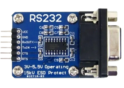
The Waveshare MAX3232 is a dual-channel RS-232 to TTL level shifter designed to facilitate communication between devices operating at different voltage levels. It converts RS-232 signal levels (±12V) to TTL levels (0-5V) and vice versa, enabling seamless interfacing between microcontrollers and serial devices such as computers, modems, and other peripherals.

Explore Projects Built with Waveshare MAX3232

Use Cirkit Designer to design, explore, and prototype these projects online. Some projects support real-time simulation. Click "Open Project" to start designing instantly!
Arduino UNO and MAX 3232 Module Controlled NE-1000 Pump System
Image of NE-1000 RS232: A project utilizing Waveshare MAX3232 in a practical application
This circuit features an Arduino UNO microcontroller interfaced with a MAX 3232 module for serial communication. The Arduino provides power and ground to the MAX 3232, and the two devices communicate via the TxD and RxD pins. The setup is likely intended for serial data transmission between the Arduino and another device.
Cirkit Designer LogoOpen Project in Cirkit Designer
ESP32-Based Multi-Sensor Health Monitoring System with Bluetooth Connectivity
Image of circuit diagram: A project utilizing Waveshare MAX3232 in a practical application
This circuit features an ESP32-WROOM-32UE microcontroller as the central processing unit, interfacing with a variety of sensors and modules. It includes a MAX30100 pulse oximeter and heart-rate sensor, an MLX90614 infrared thermometer, an HC-05 Bluetooth module for wireless communication, and a Neo 6M GPS module for location tracking. All components are powered by a common voltage supply and are connected to specific GPIO pins on the ESP32 for data exchange, with the sensors using I2C communication and the modules using UART.
Cirkit Designer LogoOpen Project in Cirkit Designer
ESP8266 NodeMCU with MAX30100 Pulse Oximeter and OLED Display
Image of SLEEP DIS : A project utilizing Waveshare MAX3232 in a practical application
This circuit features an ESP8266 NodeMCU microcontroller interfaced with a MAX30100 pulse oximeter sensor and a 0.96" OLED display. The ESP8266 communicates with both the sensor and the display over I2C, with D2 and D1 serving as the SDA and SCK lines, respectively. The MAX30100's interrupt pin is connected to D0 on the ESP8266, allowing for interrupt-driven measurements, and the OLED and MAX30100 are powered by the 3.3V output from the ESP8266.
Cirkit Designer LogoOpen Project in Cirkit Designer
ESP32-Based Health Monitoring System with MAX30102 and MAX30205 Sensors
Image of capstone: A project utilizing Waveshare MAX3232 in a practical application
This circuit features an ESP32 microcontroller as the central processing unit, interfacing with a MAX30102 pulse oximeter sensor and a MAX30205 temperature sensor via I2C communication (using GPIOs 21 and 22 for SDA and SCL, respectively). Additionally, it includes a Sim A7670c module for cellular connectivity (connected to GPIOs 16 and 17 for UART communication), and a 0.96" OLED display for data output, also on the I2C bus. All components share a common ground and are powered by a 5V supply connected to the ESP32.
Cirkit Designer LogoOpen Project in Cirkit Designer

Explore Projects Built with Waveshare MAX3232

Use Cirkit Designer to design, explore, and prototype these projects online. Some projects support real-time simulation. Click "Open Project" to start designing instantly!
Image of NE-1000 RS232: A project utilizing Waveshare MAX3232 in a practical application
Arduino UNO and MAX 3232 Module Controlled NE-1000 Pump System
This circuit features an Arduino UNO microcontroller interfaced with a MAX 3232 module for serial communication. The Arduino provides power and ground to the MAX 3232, and the two devices communicate via the TxD and RxD pins. The setup is likely intended for serial data transmission between the Arduino and another device.
Cirkit Designer LogoOpen Project in Cirkit Designer
Image of circuit diagram: A project utilizing Waveshare MAX3232 in a practical application
ESP32-Based Multi-Sensor Health Monitoring System with Bluetooth Connectivity
This circuit features an ESP32-WROOM-32UE microcontroller as the central processing unit, interfacing with a variety of sensors and modules. It includes a MAX30100 pulse oximeter and heart-rate sensor, an MLX90614 infrared thermometer, an HC-05 Bluetooth module for wireless communication, and a Neo 6M GPS module for location tracking. All components are powered by a common voltage supply and are connected to specific GPIO pins on the ESP32 for data exchange, with the sensors using I2C communication and the modules using UART.
Cirkit Designer LogoOpen Project in Cirkit Designer
Image of SLEEP DIS : A project utilizing Waveshare MAX3232 in a practical application
ESP8266 NodeMCU with MAX30100 Pulse Oximeter and OLED Display
This circuit features an ESP8266 NodeMCU microcontroller interfaced with a MAX30100 pulse oximeter sensor and a 0.96" OLED display. The ESP8266 communicates with both the sensor and the display over I2C, with D2 and D1 serving as the SDA and SCK lines, respectively. The MAX30100's interrupt pin is connected to D0 on the ESP8266, allowing for interrupt-driven measurements, and the OLED and MAX30100 are powered by the 3.3V output from the ESP8266.
Cirkit Designer LogoOpen Project in Cirkit Designer
Image of capstone: A project utilizing Waveshare MAX3232 in a practical application
ESP32-Based Health Monitoring System with MAX30102 and MAX30205 Sensors
This circuit features an ESP32 microcontroller as the central processing unit, interfacing with a MAX30102 pulse oximeter sensor and a MAX30205 temperature sensor via I2C communication (using GPIOs 21 and 22 for SDA and SCL, respectively). Additionally, it includes a Sim A7670c module for cellular connectivity (connected to GPIOs 16 and 17 for UART communication), and a 0.96" OLED display for data output, also on the I2C bus. All components share a common ground and are powered by a 5V supply connected to the ESP32.
Cirkit Designer LogoOpen Project in Cirkit Designer

Common Applications and Use Cases

  • Interfacing microcontrollers (e.g., Arduino, Raspberry Pi) with RS-232 devices.
  • Serial communication with legacy hardware such as modems and industrial equipment.
  • Debugging and testing serial communication protocols.
  • Connecting PCs to embedded systems for data exchange.

Technical Specifications

The Waveshare MAX3232 is based on the MAX3232 IC and includes the necessary capacitors for voltage conversion. Below are the key technical details:

Key Technical Details

  • Operating Voltage: 3.0V to 5.5V
  • RS-232 Voltage Levels: ±12V
  • TTL Voltage Levels: 0V to 5V
  • Baud Rate: Up to 250 kbps
  • Channels: 2 (dual transceivers)
  • Operating Temperature: -40°C to +85°C
  • Integrated Capacitors: 4 x 0.1 µF (for charge pump operation)

Pin Configuration and Descriptions

The Waveshare MAX3232 module typically has a 6-pin header for TTL connections and a DB9 connector for RS-232 connections. Below is the pinout:

TTL Side Pinout

Pin Name Description
1 VCC Power supply input (3.0V to 5.5V)
2 GND Ground
3 TXD TTL Transmit Data (to RS-232 RXD)
4 RXD TTL Receive Data (from RS-232 TXD)
5 CTS Clear to Send (optional, flow control)
6 RTS Request to Send (optional, flow control)

RS-232 Side (DB9 Connector)

Pin Name Description
2 RXD RS-232 Receive Data (to TTL TXD)
3 TXD RS-232 Transmit Data (from TTL RXD)
5 GND Ground
7 RTS Request to Send (optional, flow control)
8 CTS Clear to Send (optional, flow control)

Usage Instructions

How to Use the Component in a Circuit

  1. Power the Module: Connect the VCC pin to a 3.3V or 5V power source and the GND pin to ground.
  2. Connect TTL Signals:
    • Connect the TXD pin of the MAX3232 to the RX pin of your microcontroller.
    • Connect the RXD pin of the MAX3232 to the TX pin of your microcontroller.
  3. Connect RS-232 Signals: Use the DB9 connector to interface with the RS-232 device.
  4. Optional Flow Control: If your application requires hardware flow control, connect the CTS and RTS pins as needed.
  5. Verify Connections: Double-check all connections to ensure proper signal routing.

Important Considerations and Best Practices

  • Voltage Compatibility: Ensure the VCC voltage matches the logic level of your microcontroller (3.3V or 5V).
  • Signal Inversion: The MAX3232 automatically inverts signals as per RS-232 standards, so no additional inversion is required.
  • Baud Rate: Verify that the baud rate of the RS-232 device matches the baud rate configured in your microcontroller.
  • Cable Length: RS-232 communication is sensitive to cable length; keep cables as short as possible to avoid signal degradation.

Example: Connecting to an Arduino UNO

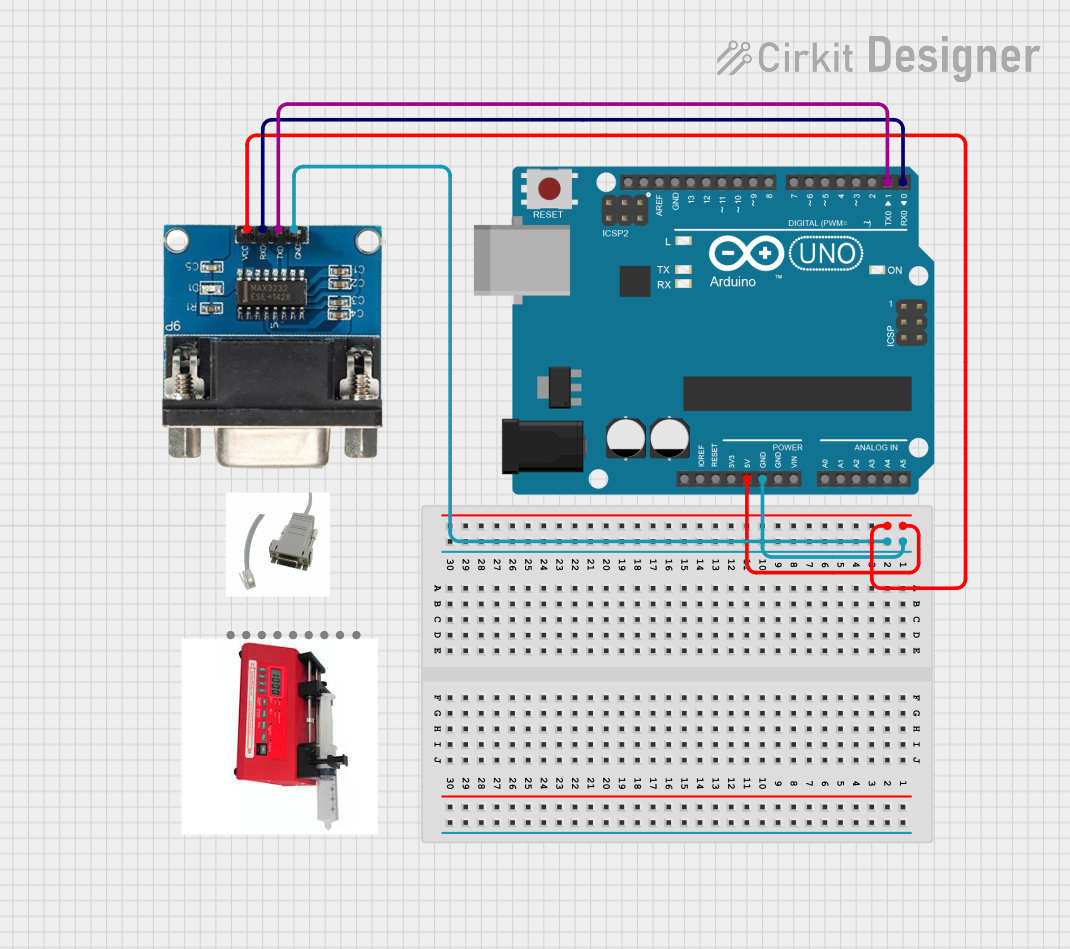
Below is an example of how to connect the Waveshare MAX3232 to an Arduino UNO and send data to an RS-232 device.

Circuit Connections

  • VCC → 5V on Arduino
  • GND → GND on Arduino
  • TXD → Pin 0 (RX) on Arduino
  • RXD → Pin 1 (TX) on Arduino
  • DB9 connector → RS-232 device

Arduino Code Example

// Example code to send and receive data using the Waveshare MAX3232
// connected to an Arduino UNO. Ensure the baud rate matches the RS-232 device.

void setup() {
  Serial.begin(9600); // Initialize serial communication at 9600 baud
  Serial.println("MAX3232 Test: Sending data to RS-232 device");
}

void loop() {
  // Send a test message to the RS-232 device
  Serial.println("Hello from Arduino!");

  // Check if data is received from the RS-232 device
  if (Serial.available() > 0) {
    String receivedData = Serial.readString(); // Read incoming data
    Serial.print("Received: ");
    Serial.println(receivedData); // Print received data to Serial Monitor
  }

  delay(1000); // Wait 1 second before sending the next message
}

Troubleshooting and FAQs

Common Issues and Solutions

  1. No Communication Between Devices

    • Cause: Incorrect wiring or mismatched baud rates.
    • Solution: Verify all connections and ensure the baud rate is the same on both devices.
  2. Data Corruption

    • Cause: Signal degradation due to long cables or noise.
    • Solution: Use shorter cables and ensure proper grounding.
  3. RS-232 Device Not Responding

    • Cause: Flow control signals (CTS/RTS) not connected or configured.
    • Solution: Check if the RS-232 device requires hardware flow control and connect the CTS and RTS pins accordingly.
  4. Module Overheating

    • Cause: Exceeding the voltage or current limits.
    • Solution: Ensure the VCC voltage is within the 3.0V to 5.5V range.

FAQs

  • Q: Can I use the MAX3232 with a 3.3V microcontroller?

    • A: Yes, the MAX3232 supports 3.0V to 5.5V operation, making it compatible with 3.3V systems.
  • Q: Do I need external capacitors for the MAX3232?

    • A: No, the Waveshare MAX3232 module includes the necessary capacitors for charge pump operation.
  • Q: What is the maximum cable length for RS-232 communication?

    • A: The RS-232 standard supports cable lengths up to 15 meters, but shorter cables are recommended for higher baud rates.
  • Q: Can I use the MAX3232 for bidirectional communication?

    • A: Yes, the MAX3232 supports full-duplex communication with its dual transceivers.

This concludes the documentation for the Waveshare MAX3232.