How to Use DRV8835 Shield Carrier: Examples, Pinouts, and Specs
Introduction
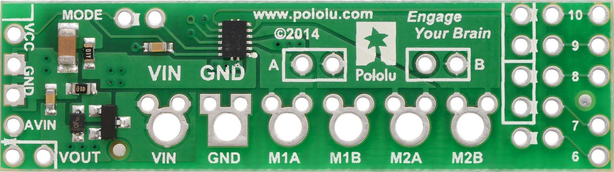
The DRV8835 Shield Carrier, manufactured by Pololu (Part ID: DRV8835), is a compact and efficient motor driver shield designed for controlling DC motors and stepper motors. It features dual H-bridge outputs, enabling bidirectional control and speed regulation. This shield is ideal for low-voltage motor control applications and is compatible with microcontroller platforms like Arduino.
Explore Projects Built with DRV8835 Shield Carrier
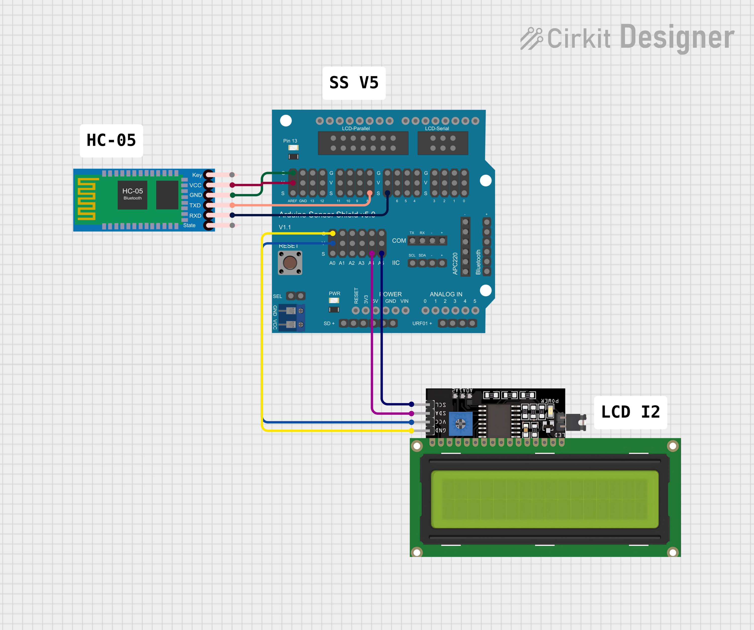

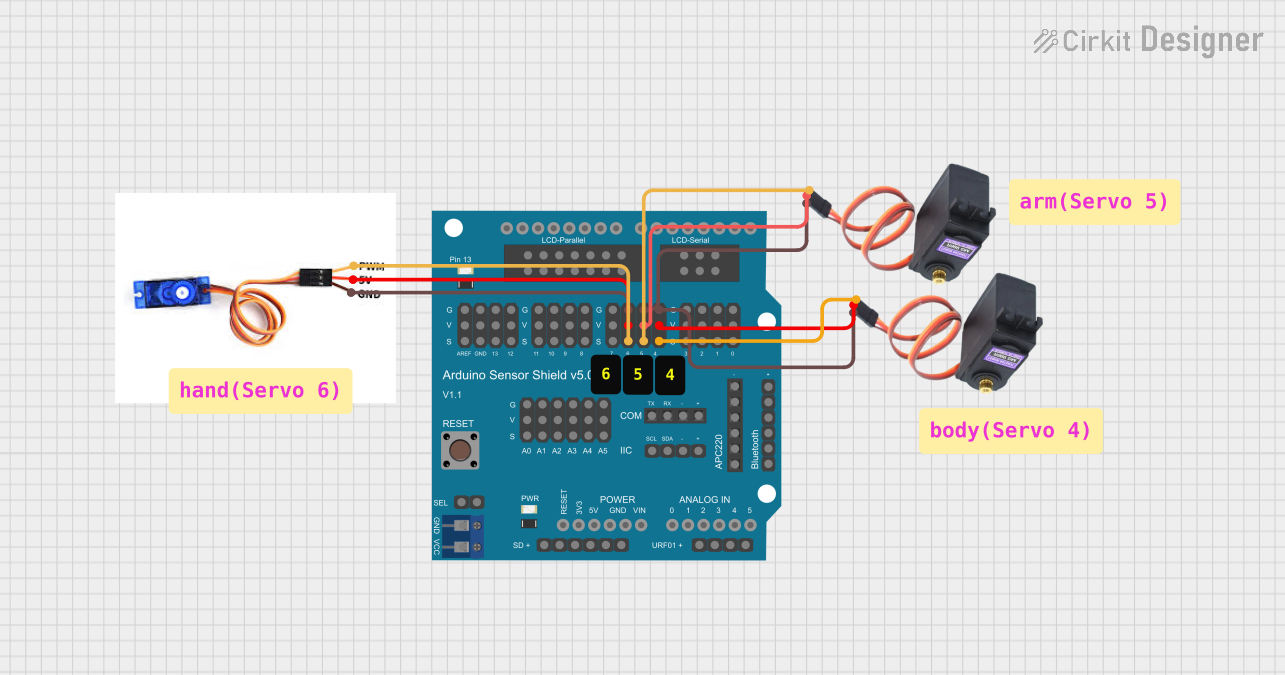
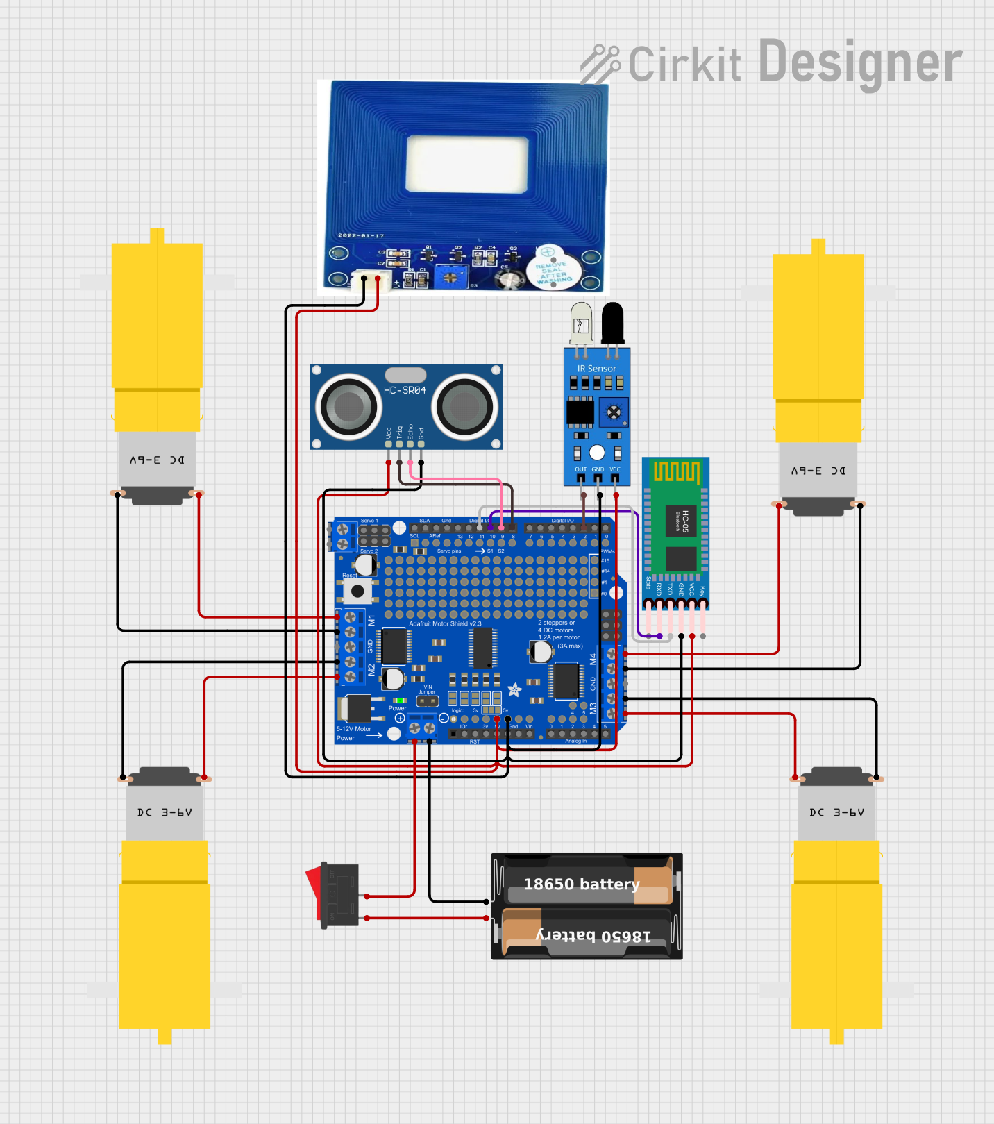
Explore Projects Built with DRV8835 Shield Carrier
Common Applications and Use Cases
- Robotics: Driving small DC motors for wheels or actuators.
- Automation: Controlling stepper motors in precision systems.
- DIY Projects: Building motorized mechanisms such as conveyor belts or robotic arms.
- Educational Projects: Learning motor control and PWM (Pulse Width Modulation) techniques.
Technical Specifications
The DRV8835 Shield Carrier is designed to provide reliable motor control with the following specifications:
Key Technical Details
| Parameter | Value |
|---|---|
| Operating Voltage Range | 2 V to 11 V |
| Continuous Output Current | 1.2 A per channel (2.4 A total) |
| Peak Output Current | 1.5 A per channel (short duration) |
| Control Interface | PWM and direction pins |
| Logic Voltage Range | 1.8 V to 7 V |
| Motor Channels | 2 (independent or combined for stepper) |
| Dimensions | 1.9" × 0.9" × 0.1" (without headers) |
| Weight | 1.2 g (without headers) |
Pin Configuration and Descriptions
The DRV8835 Shield Carrier has the following pin layout:
Motor Control Pins
| Pin Name | Description |
|---|---|
| M1A | Motor 1 output A |
| M1B | Motor 1 output B |
| M2A | Motor 2 output A |
| M2B | Motor 2 output B |
Control and Power Pins
| Pin Name | Description |
|---|---|
| VIN | Motor power supply (2 V to 11 V) |
| GND | Ground |
| VCC | Logic voltage supply (1.8 V to 7 V) |
| DIR1 | Direction control for Motor 1 |
| PWM1 | Speed control (PWM) for Motor 1 |
| DIR2 | Direction control for Motor 2 |
| PWM2 | Speed control (PWM) for Motor 2 |
Usage Instructions
How to Use the Component in a Circuit
- Power Supply: Connect the motor power supply to the
VINpin (2 V to 11 V) and ground to theGNDpin. Ensure the supply voltage matches the motor's requirements. - Logic Voltage: Provide a logic voltage (1.8 V to 7 V) to the
VCCpin. This is typically supplied by the microcontroller. - Motor Connections: Connect the motors to the
M1A,M1B,M2A, andM2Bpins. For a single stepper motor, use both channels. - Control Pins: Use the
DIR1,PWM1,DIR2, andPWM2pins to control motor direction and speed. These pins can be connected to a microcontroller's GPIO or PWM outputs.
Important Considerations and Best Practices
- Heat Dissipation: The DRV8835 can handle high currents, but prolonged operation at maximum current may cause overheating. Ensure proper ventilation or heat sinking if necessary.
- Voltage Matching: Verify that the motor voltage and current ratings are within the DRV8835's operating range.
- PWM Frequency: Use a PWM frequency between 20 kHz and 100 kHz for optimal performance and minimal audible noise.
- Reverse Polarity Protection: The shield does not include reverse polarity protection. Double-check connections before powering the circuit.
Example Code for Arduino UNO
The following example demonstrates how to control two DC motors using the DRV8835 Shield Carrier with an Arduino UNO.
// DRV8835 Motor Driver Example Code for Arduino UNO
// This code controls two DC motors using PWM and direction pins.

#define DIR1 7  // Direction pin for Motor 1
#define PWM1 6  // PWM pin for Motor 1
#define DIR2 4  // Direction pin for Motor 2
#define PWM2 5  // PWM pin for Motor 2

void setup() {
  // Set motor control pins as outputs
  pinMode(DIR1, OUTPUT);
  pinMode(PWM1, OUTPUT);
  pinMode(DIR2, OUTPUT);
  pinMode(PWM2, OUTPUT);
}

void loop() {
  // Motor 1: Forward at 50% speed
  digitalWrite(DIR1, HIGH);  // Set direction forward
  analogWrite(PWM1, 128);    // Set speed (0-255, 128 = 50%)

  // Motor 2: Reverse at 75% speed
  digitalWrite(DIR2, LOW);   // Set direction reverse
  analogWrite(PWM2, 192);    // Set speed (0-255, 192 = 75%)

  delay(2000);  // Run motors for 2 seconds

  // Stop both motors
  analogWrite(PWM1, 0);
  analogWrite(PWM2, 0);

  delay(1000);  // Wait for 1 second before repeating
}
Troubleshooting and FAQs
Common Issues and Solutions
Motors Not Running:
- Verify that the power supply is connected and within the specified voltage range.
- Check the motor connections to the
M1A,M1B,M2A, andM2Bpins. - Ensure the control pins (
DIRandPWM) are correctly configured in the code.
Overheating:
- Reduce the motor load or operating current.
- Add a heat sink or improve ventilation around the shield.
Erratic Motor Behavior:
- Check for loose or faulty connections.
- Ensure the PWM frequency is within the recommended range (20 kHz to 100 kHz).
No Response from Shield:
- Confirm that the logic voltage (
VCC) is supplied and matches the microcontroller's logic level. - Test the control pins with a multimeter to ensure proper signal output.
- Confirm that the logic voltage (
FAQs
Q: Can the DRV8835 Shield Carrier drive stepper motors?
A: Yes, the DRV8835 can drive a single bipolar stepper motor by using both motor channels. Ensure proper wiring and control sequencing.
Q: What is the maximum current the DRV8835 can handle?
A: The DRV8835 can handle up to 1.2 A continuously per channel and 1.5 A peak for short durations.
Q: Is the shield compatible with 3.3 V logic microcontrollers?
A: Yes, the DRV8835 supports logic voltages as low as 1.8 V, making it compatible with 3.3 V and 5 V systems.
Q: Can I use the shield with a Raspberry Pi?
A: Yes, the DRV8835 can be controlled by a Raspberry Pi, but additional software libraries may be required for PWM control.