
How to Use Wiring USB Adapter: Examples, Pinouts, and Specs

 Design with Wiring USB Adapter in Cirkit Designer
Introduction
The Wiring USB Adapter is a versatile device designed to enable the connection of USB cables to various electronic components. It serves as a bridge for both data transfer and power supply, making it an essential tool for prototyping, testing, and integrating USB-enabled devices into electronic projects. Its compact design and ease of use make it suitable for hobbyists, engineers, and developers alike.
Explore Projects Built with Wiring USB Adapter
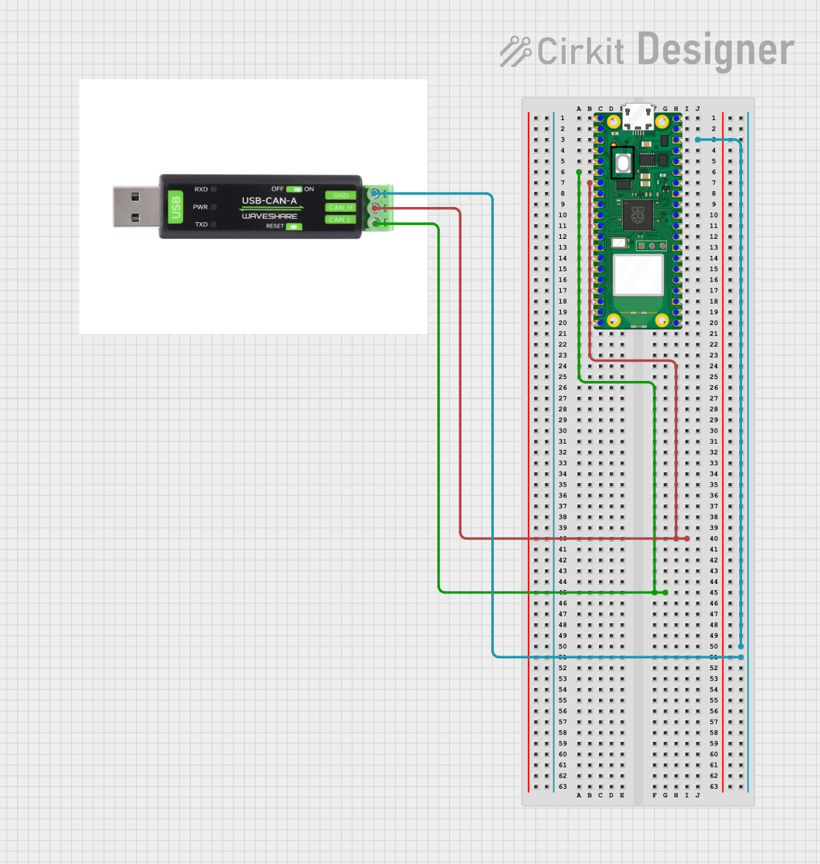 Open Project in Cirkit Designer
 Open Project in Cirkit Designer
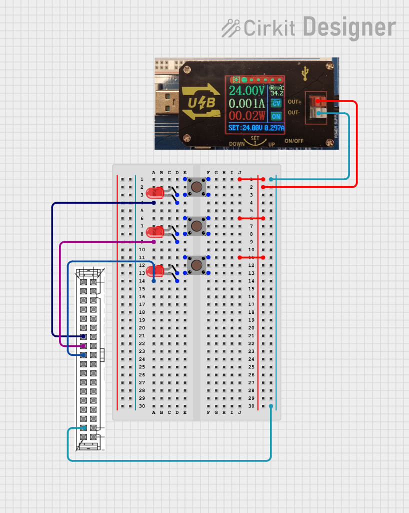 Open Project in Cirkit Designer
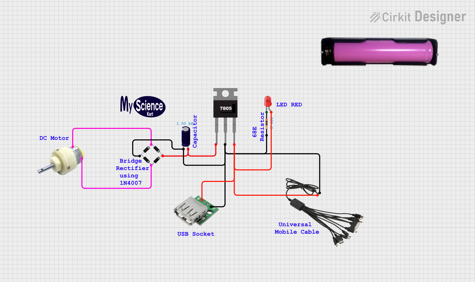 Open Project in Cirkit Designer
Explore Projects Built with Wiring USB Adapter
Open Project in Cirkit DesignerOpen Project in Cirkit DesignerOpen Project in Cirkit DesignerOpen Project in Cirkit DesignerCommon Applications and Use Cases
- Connecting microcontrollers (e.g., Arduino, Raspberry Pi) to USB devices.
- Powering small electronic circuits via USB power.
- Facilitating data communication between USB peripherals and embedded systems.
- Prototyping USB-based projects, such as USB keyboards, mice, or storage devices.
Technical Specifications
The Wiring USB Adapter is designed to meet the needs of a wide range of USB-based applications. Below are its key technical details:
General Specifications
| Parameter | Value |
|---|---|
| USB Standard | USB 2.0 (backward compatible) |
| Input Voltage (V_in) | 5V DC (via USB connection) |
| Output Voltage (V_out) | 5V DC |
| Maximum Current | 500mA (standard USB port) |
| Connector Type | USB Type-A or Type-B |
| Dimensions | 30mm x 20mm x 10mm |
Pin Configuration and Descriptions
The Wiring USB Adapter typically features a 4-pin USB interface. Below is the pinout for a standard USB Type-A connector:
| Pin Number | Name | Description |
|---|---|---|
| 1 | VCC | +5V power supply |
| 2 | D- | Data line (negative) |
| 3 | D+ | Data line (positive) |
| 4 | GND | Ground |
Usage Instructions
How to Use the Wiring USB Adapter in a Circuit
- Connect the USB Adapter to a USB Port: Plug the adapter into a USB port on your computer, power bank, or USB wall adapter to provide power and/or data connectivity.
- Connect to Your Circuit:
- Use the VCC and GND pins to supply 5V power to your circuit.
- Use the D+ and D- pins for data communication if required.
- Verify Connections: Ensure all connections are secure and match the pinout specifications to avoid damage to the adapter or connected devices.
Important Considerations and Best Practices
- Power Limitations: Do not exceed the maximum current rating of 500mA to prevent overheating or damage.
- Data Communication: Ensure proper grounding and shielding for reliable data transfer, especially in noisy environments.
- USB Standards: While the adapter supports USB 2.0, it is backward compatible with USB 1.1 devices. However, it may not support USB 3.0 speeds.
- Arduino Integration: The adapter can be used to power and communicate with an Arduino UNO. Below is an example of how to use it with an Arduino.
Example: Using the Wiring USB Adapter with Arduino UNO
The following code demonstrates how to use the Wiring USB Adapter to send data from an Arduino UNO to a computer via USB.
// Example: Sending data from Arduino UNO to a computer via USB
// This code sends a simple message to the Serial Monitor.

void setup() {
  Serial.begin(9600); // Initialize serial communication at 9600 baud
  delay(1000);        // Wait for the serial connection to stabilize
  Serial.println("Wiring USB Adapter Test: Connection Successful!");
}

void loop() {
  Serial.println("Hello from Arduino!"); // Send a message every second
  delay(1000);                          // Wait for 1 second
}
Note: Ensure the Wiring USB Adapter is properly connected to the Arduino UNO's USB port. Open the Serial Monitor in the Arduino IDE to view the messages.
Troubleshooting and FAQs
Common Issues and Solutions
No Power to the Circuit:
- Cause: Loose or incorrect connections.
- Solution: Verify that the USB adapter is securely connected to the power source and that the VCC and GND pins are correctly wired.
Data Transfer Fails:
- Cause: Incorrect wiring of D+ and D- pins or poor grounding.
- Solution: Double-check the connections and ensure proper grounding. Use shorter cables to reduce signal degradation.
Overheating:
- Cause: Excessive current draw from the USB port.
- Solution: Ensure the connected circuit does not exceed the 500mA current limit. Use a powered USB hub if additional current is required.
Device Not Recognized by Computer:
- Cause: Faulty USB cable or incompatible device.
- Solution: Test with a different USB cable or device. Ensure the device is compatible with USB 2.0.
FAQs
Q: Can the Wiring USB Adapter be used with USB 3.0 devices?
- A: Yes, but it will operate at USB 2.0 speeds.
Q: Is the adapter suitable for charging devices?
- A: Yes, it can supply 5V power for charging small devices, but it is not recommended for high-power devices like tablets.
Q: Can I use the adapter for both power and data simultaneously?
- A: Yes, the adapter supports simultaneous power supply and data transfer.
By following this documentation, you can effectively integrate the Wiring USB Adapter into your projects and troubleshoot common issues with ease.