How to Use Charging Module: Examples, Pinouts, and Specs
Introduction
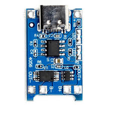
The TP4056 Charging Module, manufactured by Arduino, is a compact and efficient device designed to manage the charging of lithium-ion and lithium-polymer batteries. It ensures safe and efficient charging by incorporating features such as overcharge protection, voltage regulation, and current control. This module is widely used in battery-powered projects due to its reliability and ease of integration.
Explore Projects Built with Charging Module


Explore Projects Built with Charging Module
Common Applications and Use Cases
- Charging single-cell lithium-ion or lithium-polymer batteries.
- Power management in portable electronic devices.
- DIY electronics projects requiring rechargeable battery support.
- Battery-powered IoT devices and wearables.
- Backup power systems and small robotics.
Technical Specifications
The TP4056 Charging Module is designed to provide a safe and efficient charging solution. Below are its key technical details:
Key Technical Details
| Parameter | Value |
|---|---|
| Input Voltage Range | 4.5V to 5.5V |
| Charging Voltage | 4.2V ± 1% |
| Maximum Charging Current | 1A (adjustable via resistor) |
| Battery Type Supported | Single-cell Li-ion/LiPo |
| Overcharge Protection | Yes |
| Over-discharge Protection | Yes |
| Operating Temperature | -10°C to +85°C |
| Dimensions | ~25mm x 19mm x 10mm |
Pin Configuration and Descriptions
The TP4056 Charging Module has six pins, as described in the table below:
| Pin Name | Type | Description |
|---|---|---|
| IN+ | Input | Positive input voltage (4.5V to 5.5V). Connect to a USB 5V source or adapter. |
| IN- | Input | Negative input voltage (ground). Connect to the ground of the power source. |
| BAT+ | Output | Positive terminal for the battery connection. |
| BAT- | Output | Negative terminal for the battery connection. |
| OUT+ | Output | Positive output voltage for the load (connected to the battery). |
| OUT- | Output | Negative output voltage for the load (connected to the battery). |
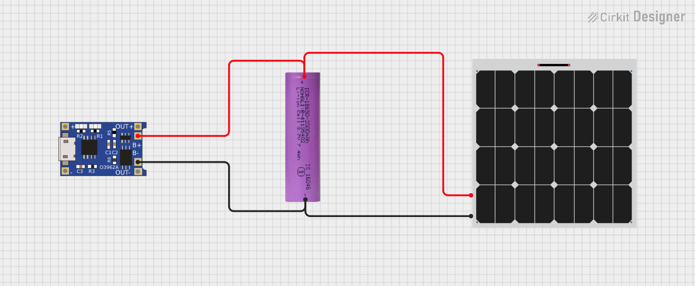
Usage Instructions
How to Use the TP4056 Charging Module in a Circuit
Connect the Power Source:
- Connect the
IN+pin to the positive terminal of a 5V power source (e.g., USB adapter). - Connect the
IN-pin to the ground of the power source.
- Connect the
Connect the Battery:
- Attach the positive terminal of the battery to the
BAT+pin. - Attach the negative terminal of the battery to the
BAT-pin.
- Attach the positive terminal of the battery to the
Connect the Load (Optional):
- If you want to power a load while charging the battery, connect the load's positive terminal to
OUT+and the negative terminal toOUT-.
- If you want to power a load while charging the battery, connect the load's positive terminal to
Monitor the Charging Status:
- The module has two onboard LEDs:
- Red LED: Indicates charging is in progress.
- Blue LED: Indicates charging is complete.
- The module has two onboard LEDs:
Important Considerations and Best Practices
- Ensure the input voltage does not exceed 5.5V to avoid damaging the module.
- Use a heat sink or proper ventilation if charging at high currents (close to 1A).
- Do not reverse the polarity of the battery connections, as this may damage the module.
- For adjustable charging current, replace the onboard resistor (default is 1.2kΩ for 1A charging).
- Avoid using the module with batteries that have a capacity below 500mAh, as the default charging current may be too high.
Example: Using the TP4056 with an Arduino UNO
The TP4056 can be used to charge a battery that powers an Arduino UNO. Below is an example of how to monitor the charging status using the Arduino:
// Example code to monitor TP4056 charging status with Arduino UNO
// Connect the TP4056 module's status pins to Arduino digital pins

const int chargingPin = 2; // Connect to TP4056 Red LED (charging status)
const int chargedPin = 3;  // Connect to TP4056 Blue LED (charged status)

void setup() {
  pinMode(chargingPin, INPUT); // Set chargingPin as input
  pinMode(chargedPin, INPUT);  // Set chargedPin as input
  Serial.begin(9600);          // Initialize serial communication
}

void loop() {
  bool isCharging = digitalRead(chargingPin); // Read charging status
  bool isCharged = digitalRead(chargedPin);  // Read charged status

  if (isCharging == LOW) {
    // Red LED is active low, so LOW means charging
    Serial.println("Battery is charging...");
  } else if (isCharged == LOW) {
    // Blue LED is active low, so LOW means fully charged
    Serial.println("Battery is fully charged!");
  } else {
    Serial.println("No battery detected or idle state.");
  }

  delay(1000); // Wait for 1 second before checking again
}
Troubleshooting and FAQs
Common Issues and Solutions
The module overheats during charging.
- Solution: Ensure the input voltage does not exceed 5.5V. If charging at high currents, use proper ventilation or a heat sink.
The battery does not charge.
- Solution: Check the battery connections to
BAT+andBAT-. Ensure the battery is not damaged or over-discharged.
- Solution: Check the battery connections to
The LEDs do not light up.
- Solution: Verify the input voltage and connections to
IN+andIN-. Ensure the power source is functioning correctly.
- Solution: Verify the input voltage and connections to
The module stops charging before the battery is full.
- Solution: Check the battery's specifications. The TP4056 is designed for single-cell lithium-ion or lithium-polymer batteries only.
FAQs
Can I use the TP4056 to charge multiple batteries in series?
No, the TP4056 is designed for single-cell batteries only. Charging multiple batteries in series may result in uneven charging and damage.How do I adjust the charging current?
Replace the onboard resistor (Rprog) with a different value. For example, a 2kΩ resistor sets the charging current to 500mA.Can I use the module without a battery?
No, the TP4056 requires a battery to function properly. It is not designed to act as a standalone power supply.
By following this documentation, you can safely and effectively use the TP4056 Charging Module in your projects.