How to Use Solar Panel: Examples, Pinouts, and Specs
Introduction
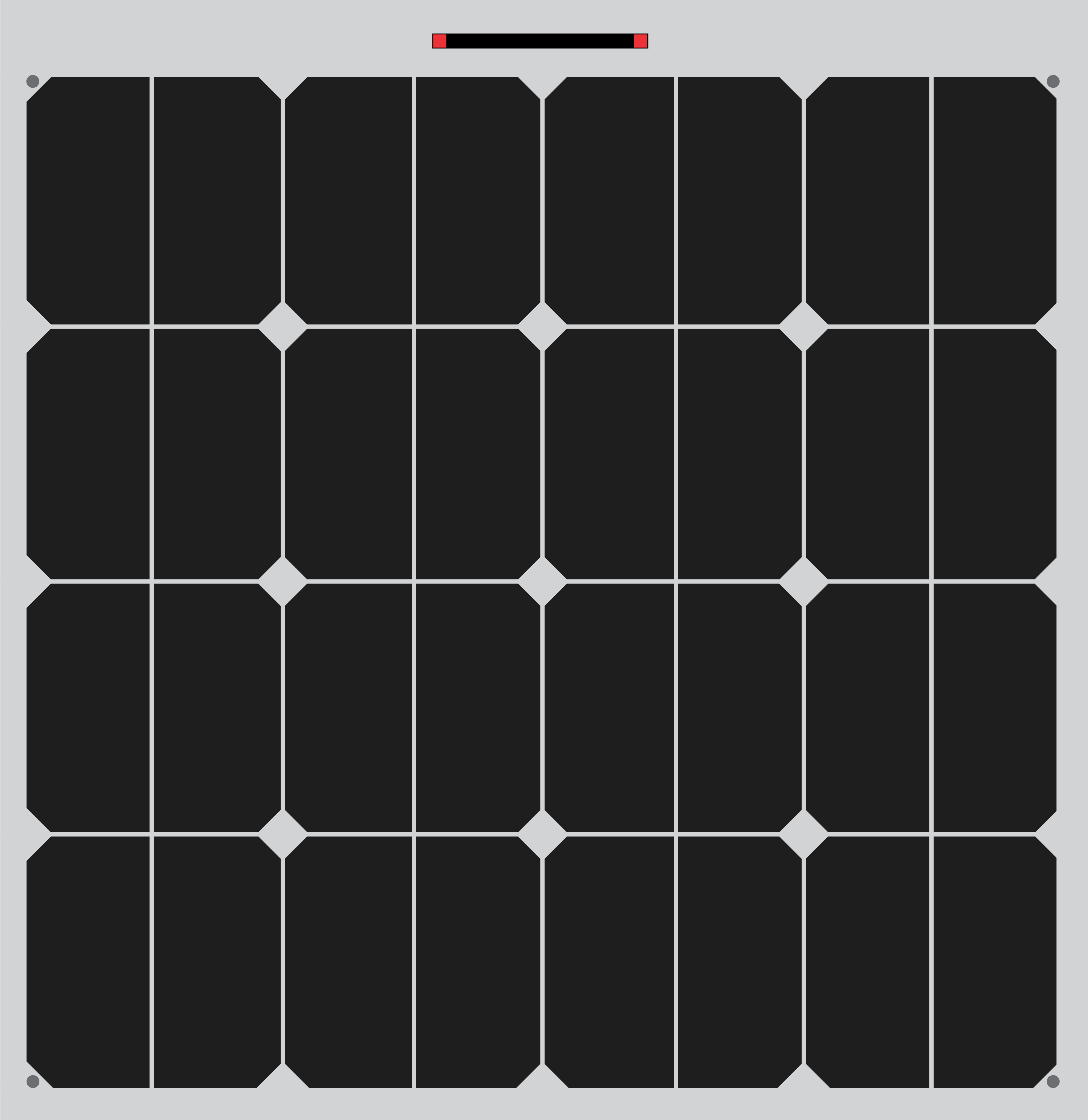
A solar panel is a device that converts light energy from the sun into electrical energy through the photovoltaic effect. Solar panels are composed of multiple solar cells made from semiconductor materials, typically silicon. They are widely used in a variety of applications, ranging from small-scale systems like solar-powered calculators and garden lights to large-scale solar farms that contribute to the electrical grid.
Explore Projects Built with Solar Panel
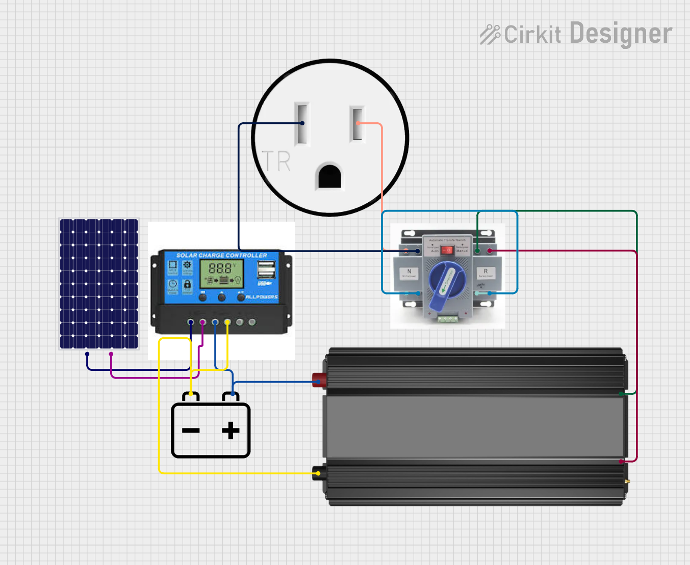

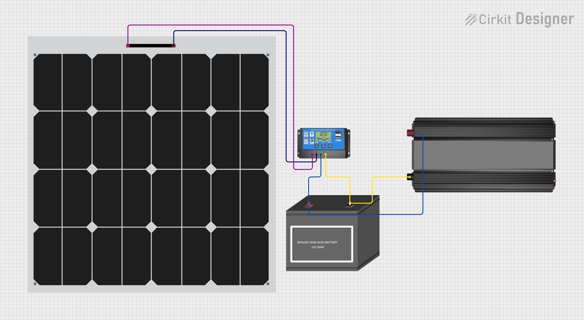
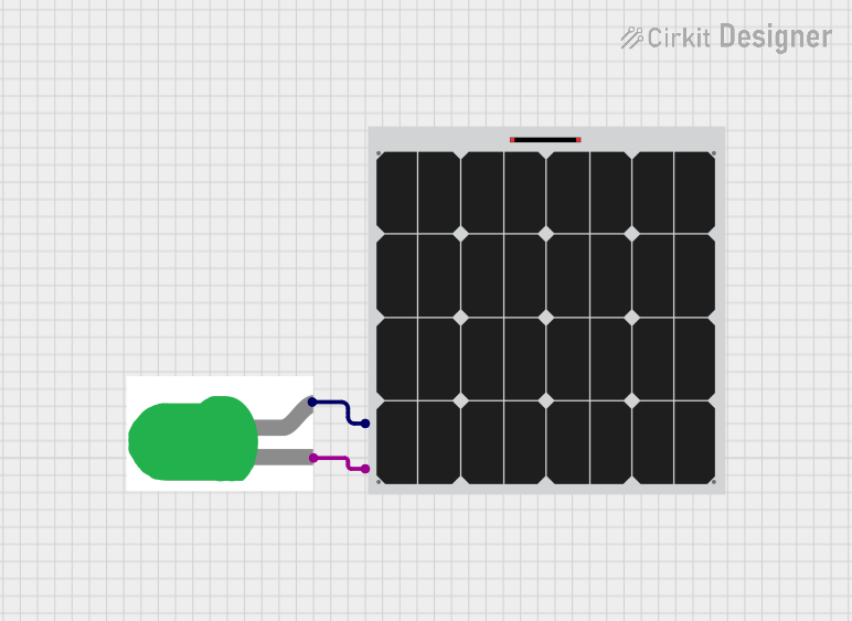
Explore Projects Built with Solar Panel
Common Applications and Use Cases
- Residential and commercial solar installations for electricity generation
- Remote power systems for telecommunications and off-grid locations
- Portable charging systems for devices and batteries
- Solar-powered lighting and appliances
- Integration with microcontroller projects, such as Arduino-based systems
Technical Specifications
Key Technical Details
| Specification | Description |
|---|---|
| Nominal Voltage | 12V, 24V, etc. (depends on the panel design) |
| Power Output | 100W, 200W, etc. (varies by size and efficiency) |
| Current Rating | 5A, 10A, etc. (depends on the panel capacity) |
| Open-Circuit Voltage (Voc) | Slightly higher than nominal voltage |
| Short-Circuit Current (Isc) | Maximum current the panel can provide |
| Dimensions | Length x Width x Depth (mm) |
| Weight | Specified in kilograms or pounds |
| Cell Type | Monocrystalline, Polycrystalline, Thin-film, etc. |
| Connector Type | MC4, Anderson, etc. (varies by manufacturer) |
| Operating Temperature Range | -40°C to +85°C (typical) |
Pin Configuration and Descriptions
Solar panels typically come with positive and negative terminals for connecting to a circuit. The terminals may be in the form of wires, junction boxes, or connectors like MC4.
| Pin/Connector | Description |
|---|---|
| Positive (+) | Power output terminal |
| Negative (-) | Ground terminal |
Usage Instructions
How to Use the Solar Panel in a Circuit
Mounting the Solar Panel: Ensure the solar panel is mounted at an angle facing the sun for maximum exposure. Use mounting brackets and ensure the panel is securely attached.
Wiring: Connect the positive terminal of the solar panel to the positive input of a charge controller, and the negative terminal to the negative input. This helps regulate the power going to the battery.
Connecting to a Battery: The charge controller's output should be connected to a battery's positive and negative terminals to store the generated electricity.
Load Connection: Connect the load to the battery through the charge controller, ensuring that the load does not exceed the panel's power rating.
Important Considerations and Best Practices
- Always use a charge controller to prevent battery overcharging and damage.
- Ensure the solar panel's voltage and current ratings are compatible with the system's components.
- Use proper gauge wires to handle the expected current and minimize voltage drop.
- Consider environmental factors such as shading, dust, and temperature, which can affect performance.
- Regularly clean the panel surface to maintain efficiency.
Troubleshooting and FAQs
Common Issues
- Low Power Output: Check for shading, dirt, or obstructions on the panel. Ensure proper orientation towards the sun.
- No Power Output: Verify all connections, check for damage to the panel or wiring, and ensure the charge controller is functioning.
- Intermittent Power: Inspect for loose connections and check the charge controller settings.
Solutions and Tips
- Clean the panel surface with a soft cloth and soapy water to remove debris.
- Use a multimeter to check the open-circuit voltage and short-circuit current to ensure the panel is operating within specifications.
- Ensure the system components are rated for outdoor use and are weatherproof.
FAQs
Q: Can I connect multiple solar panels together? A: Yes, panels can be connected in series to increase voltage or in parallel to increase current, depending on your system's needs.
Q: Do I need a charge controller? A: A charge controller is highly recommended to protect the battery from overcharging and to ensure the longevity of your system.
Q: How do I determine the size of the solar panel I need? A: Calculate the total energy consumption of your load in watt-hours and match it with the solar panel's output, considering the average sunlight hours.
Q: Can I use a solar panel with an Arduino? A: Yes, but you will need a voltage regulator or a charge controller to ensure the voltage is within the Arduino's operating range.
Example Arduino Connection Code
// This example assumes the use of a 6V solar panel connected to an Arduino UNO
// through a 5V voltage regulator to power the board safely.

void setup() {
  // Initialize the serial communication to check the voltage
  Serial.begin(9600);
}

void loop() {
  int sensorValue = analogRead(A0); // Read the solar panel voltage
  float voltage = sensorValue * (5.0 / 1023.0); // Convert to voltage
  Serial.println(voltage); // Print the voltage to the Serial Monitor
  delay(1000); // Wait for a second
}
Note: The above code is a simple demonstration of reading the voltage from a solar panel using an Arduino. In a practical application, you would need additional components like a charge controller and a battery to create a functional solar power system.