How to Use ILI9341 TFT display: Examples, Pinouts, and Specs

Introduction
The ILI9341 TFT display is a versatile and colorful display module commonly used in embedded systems and DIY electronics projects. It features a Thin Film Transistor (TFT) screen that is capable of displaying full-color graphics and text. The display is driven by the ILI9341 controller, which facilitates communication between the display and a microcontroller, such as an Arduino UNO, through a Serial Peripheral Interface (SPI) or 8/16-bit parallel interface.
Explore Projects Built with ILI9341 TFT display


Explore Projects Built with ILI9341 TFT display
Common Applications and Use Cases
- User interfaces for embedded systems
- Display output for sensors and data
- Portable game consoles
- DIY smartwatches
- Home automation control panels
Technical Specifications
Key Technical Details
- Display Size: Typically 2.4 to 3.2 inches diagonally
- Resolution: 240x320 pixels
- Interface: SPI / 8/16-bit parallel
- Color Depth: 16-bit (65,536 colors)
- Operating Voltage: 3.3V (5V tolerant with level shifters)
- Logic Level: 3.3V
Pin Configuration and Descriptions
| Pin Name | Description |
|---|---|
| VCC | Power supply (3.3V input) |
| GND | Ground |
| CS | Chip Select (active low) |
| RESET | Reset (active low) |
| DC/RS | Data/Command control pin |
| SDI/MOSI | Serial Data Input / Master Out Slave In |
| SCK | Serial Clock |
| LED | Backlight control (anode) |
| SDO/MISO | Serial Data Output / Master In Slave Out (optional) |
Usage Instructions
How to Use the Component in a Circuit
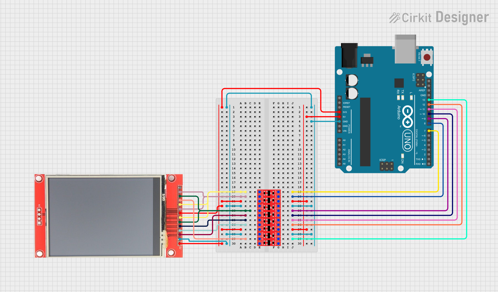
Power Connections: Connect VCC to 3.3V and GND to the ground of your power supply. If using with a 5V system like an Arduino UNO, ensure you use level shifters or voltage regulators to avoid damaging the display.
Data Connections: For SPI communication, connect the SDI/MOSI, SCK, and SDO/MISO (if reading from the display) to the corresponding SPI pins on your microcontroller.
Control Pins: Connect CS to the chip select pin, RESET to the reset pin, and DC/RS to the data/command pin on your microcontroller.
Backlight: Connect LED to a digital pin for backlight control or directly to 3.3V for constant backlight.
Important Considerations and Best Practices
- Always check the voltage levels to prevent damage to the display.
- Use a current limiting resistor with the LED pin if connecting directly to a power source.
- Avoid exposing the display to direct sunlight or high temperatures to prevent damage.
- When using SPI, ensure that the SPI mode and clock speed are correctly set for the ILI9341.
Example Code for Arduino UNO
#include <Adafruit_GFX.h> // Core graphics library
#include <Adafruit_ILI9341.h> // Hardware-specific library
// For the Adafruit shield, these are the default.
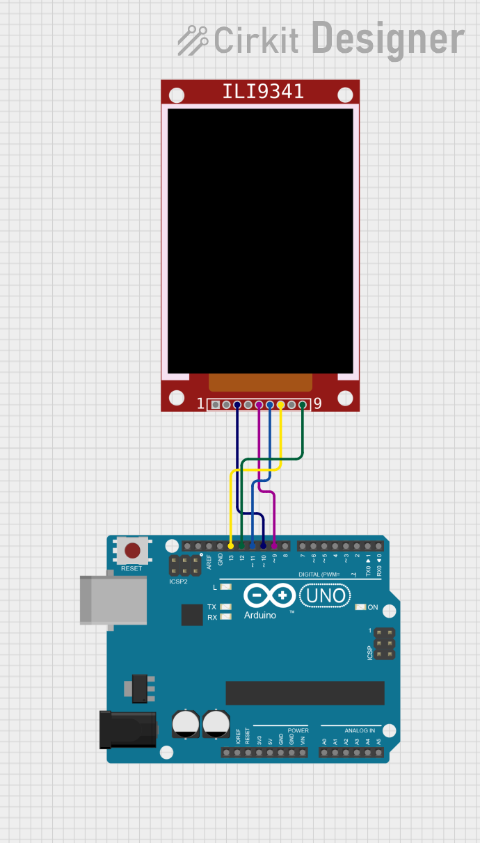
#define TFT_CS 10
#define TFT_RST 9 // You can also connect this to the Arduino reset
// in which case, set this #define pin to -1!
#define TFT_DC 8
Adafruit_ILI9341 tft = Adafruit_ILI9341(TFT_CS, TFT_DC, TFT_RST);
void setup() {
Serial.begin(9600);
tft.begin();
// Make sure the orientation is correct
tft.setRotation(1);
// Fill the screen with black color
tft.fillScreen(ILI9341_BLACK);
}
void loop() {
// Check the Adafruit GFX library for more graphics functions
tft.setCursor(0, 0);
tft.setTextColor(ILI9341_WHITE);
tft.setTextSize(1);
tft.println("Hello, World!");
}
Troubleshooting and FAQs
Common Issues
- Display not powering on: Check the power connections and ensure the voltage is 3.3V.
- No display output: Verify that the SPI connections are correct and the chip select pin is being controlled properly.
- Distorted images or text: Ensure that the library and microcontroller are configured for the correct SPI mode and clock speed.
Solutions and Tips for Troubleshooting
- Double-check wiring, especially the SPI and control pins.
- Make sure that the correct driver library (
Adafruit_ILI9341) is installed in your Arduino IDE. - Reset the display by toggling the RESET pin if the display is not responding correctly.
FAQs
Q: Can I use the ILI9341 display with a 5V microcontroller?
A: Yes, but you must use level shifters or voltage regulators to bring the logic levels down to 3.3V to avoid damaging the display.
Q: How can I control the brightness of the display?
A: The brightness can be controlled by applying PWM to the LED backlight pin.
Q: What should I do if I see white dots or lines on the display?
A: White dots or lines can indicate a faulty connection or a damaged display. Check the connections first, and if the problem persists, the display may need to be replaced.