How to Use dc to dc boost convater: Examples, Pinouts, and Specs
Introduction
A DC to DC boost converter is an electronic circuit designed to step up (increase) the voltage from its input (supply) to its output (load) while maintaining the power balance (input power equals output power, minus losses). These converters are widely used in portable electronic devices, such as mobile phones, laptops, and in systems where the power supply voltage is lower than the required voltage at the load. They are also essential in renewable energy applications, such as solar power systems, where they help in maximizing the energy extraction from solar panels by boosting the voltage to the required level for storage or inversion.
Explore Projects Built with dc to dc boost convater


Explore Projects Built with dc to dc boost convater
Technical Specifications
Key Technical Details
- Input Voltage Range: Typically, the range within which the converter can operate effectively.
- Output Voltage Range: The range of voltages the converter can output.
- Efficiency: The ratio of output power to input power, usually expressed as a percentage.
- Switching Frequency: The frequency at which the converter's internal switch operates.
- Maximum Output Current: The maximum current the converter can provide to the load.
- Operating Temperature Range: The range of ambient temperatures within which the converter can operate safely.
Pin Configuration and Descriptions
| Pin Number | Name | Description |
|---|---|---|
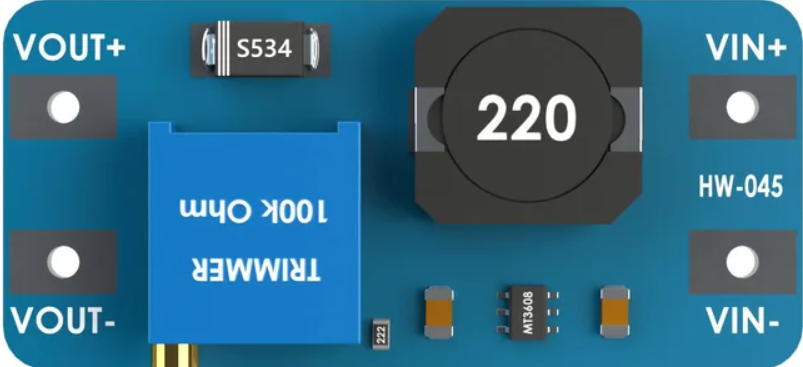
| 1 | VIN | Input voltage to the converter. Connect to the DC power source. |
| 2 | GND | Ground reference for the circuit. Connect to the power source ground and load ground. |
| 3 | VOUT | Output voltage from the converter. Connect to the load. |
| 4 | EN | Enable pin for turning the converter on or off. A high signal typically enables the converter. |
| 5 | SW | Switch pin connected to the internal switch. Usually not externally accessible. |
| 6 | FB | Feedback pin used for regulation. Connect to a voltage divider from the output to set the desired voltage. |
Usage Instructions
How to Use the Component in a Circuit
- Input Power Connection: Connect the positive terminal of the DC power source to the VIN pin and the negative terminal to the GND pin.
- Output Load Connection: Connect the load to the VOUT pin and the other side of the load to the GND pin.
- Setting Output Voltage: Use a voltage divider from VOUT to FB to set the desired output voltage according to the converter's feedback reference voltage.
- Enable the Converter: Apply a high signal to the EN pin to turn on the converter. A low signal or ground will disable the converter.
Important Considerations and Best Practices
- Input Capacitor: Place a capacitor close to the VIN and GND pins to filter input voltage spikes and improve stability.
- Output Capacitor: Place a capacitor close to the VOUT and GND pins to smooth out the output voltage and reduce voltage ripple.
- Heat Management: Ensure adequate cooling for the converter, as efficiency losses often result in heat generation.
- Inductor Selection: Choose an inductor with a current rating above the maximum output current and a low series resistance to minimize losses.
- Switching Frequency: Be aware that higher switching frequencies can improve response times but may increase electromagnetic interference (EMI) and reduce efficiency.
Troubleshooting and FAQs
Common Issues
- Insufficient Output Voltage: Check the voltage divider on the FB pin and ensure that the input voltage is within specifications.
- Overheating: Ensure that the current draw is within the converter's limits and that there is adequate heat dissipation.
- Output Voltage Ripple: Increase the size of the output capacitor or add additional capacitors to reduce ripple.
Solutions and Tips for Troubleshooting
- Check Connections: Verify all connections are secure and correct.
- Measure Input Voltage: Ensure the input voltage is within the specified range for the converter.
- Inspect Components: Look for signs of damage or overheating on the converter and surrounding components.
FAQs
Q: Can I use a boost converter to charge batteries? A: Yes, but ensure that the output voltage is appropriate for the battery and that you have proper charging circuitry in place.
Q: What happens if I exceed the maximum input voltage? A: Exceeding the maximum input voltage can damage the converter. Always stay within the recommended voltage range.
Q: How can I adjust the output voltage? A: Adjust the ratio of the resistors in the voltage divider connected to the FB pin to change the feedback voltage and thus the output voltage.
Example Code for Arduino UNO
// Example code to control a DC to DC boost converter with an Arduino UNO
// This example assumes the use of an enable pin on the boost converter.

const int enablePin = 9; // Connect to the EN pin of the boost converter

void setup() {
  pinMode(enablePin, OUTPUT);
  digitalWrite(enablePin, LOW); // Start with the converter disabled
}

void loop() {
  // Enable the boost converter
  digitalWrite(enablePin, HIGH);
  delay(5000); // Keep the converter on for 5 seconds

  // Disable the boost converter
  digitalWrite(enablePin, LOW);
  delay(5000); // Keep the converter off for 5 seconds
}
Remember to adjust the pin number to match your actual circuit configuration. The code above simply turns the boost converter on and off at 5-second intervals.