How to Use Relay board for Micro:bit: Examples, Pinouts, and Specs
Introduction
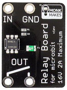
The Relay Board for Micro:bit by MonkMakes (Part ID: 1) is a versatile electronic module designed to enable the Micro:bit to control high-power devices. This relay board acts as an electrically operated switch, allowing the Micro:bit to toggle devices such as lights, motors, or other appliances on and off using low-power signals. It is an essential component for projects requiring the control of external devices that operate at higher voltages or currents than the Micro:bit can handle directly.
Explore Projects Built with Relay board for Micro:bit
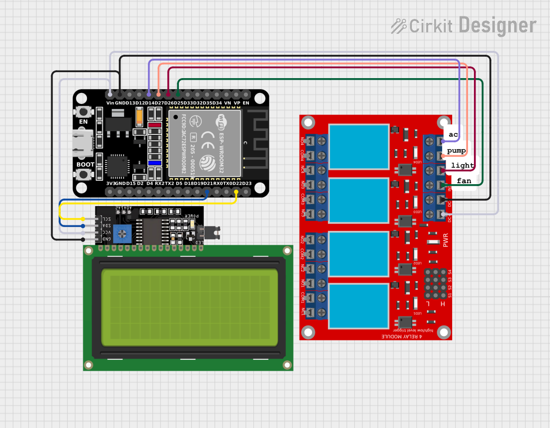
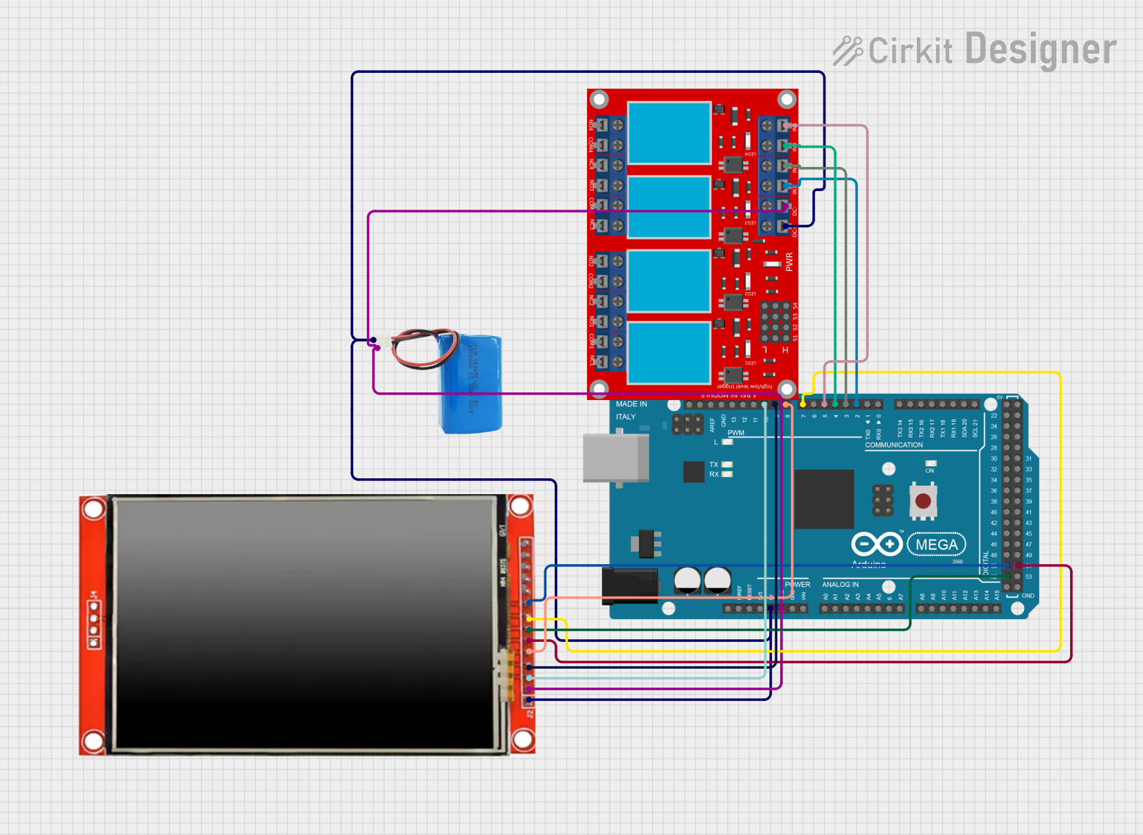
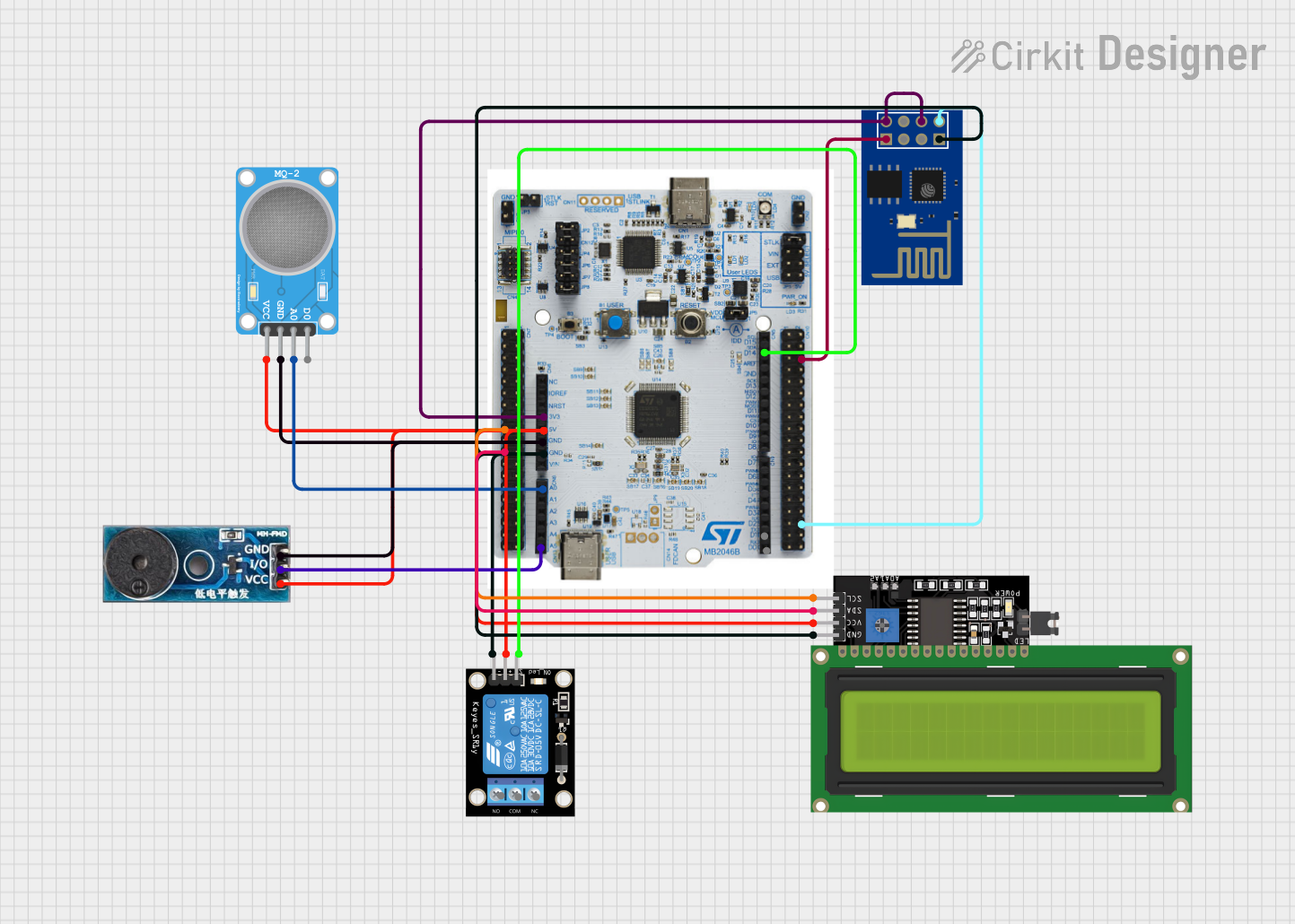
Explore Projects Built with Relay board for Micro:bit
Common Applications and Use Cases
- Home automation projects (e.g., controlling lights or fans)
- Robotics (e.g., activating motors or actuators)
- IoT (Internet of Things) applications
- Educational projects to demonstrate relay operation
- Prototyping circuits that require high-power switching
Technical Specifications
The following table outlines the key technical details of the Relay Board for Micro:bit:
| Specification | Details |
|---|---|
| Manufacturer | MonkMakes |
| Part ID | 1 |
| Operating Voltage | 3.3V to 5V |
| Trigger Voltage | 3.3V (compatible with Micro:bit GPIO) |
| Maximum Switching Voltage | 240V AC / 30V DC |
| Maximum Switching Current | 10A |
| Relay Type | SPDT (Single Pole Double Throw) |
| Dimensions | 50mm x 40mm x 20mm |
| Weight | 20g |
Pin Configuration and Descriptions
The relay board has the following pin connections:
| Pin | Name | Description |
|---|---|---|
| 1 | VCC | Power input (3.3V to 5V). Connect to the Micro:bit's 3V pin. |
| 2 | GND | Ground connection. Connect to the Micro:bit's GND pin. |
| 3 | IN | Signal input. Connect to a GPIO pin on the Micro:bit to control the relay. |
| 4 | COM (Common) | Common terminal of the relay switch. |
| 5 | NO (Normally Open) | Normally open terminal. Connect to the device to be powered when the relay is active. |
| 6 | NC (Normally Closed) | Normally closed terminal. Connect to the device to be powered when the relay is inactive. |
Usage Instructions
How to Use the Relay Board in a Circuit
Connect the Relay Board to the Micro:bit:
- Connect the
VCCpin of the relay board to the3Vpin on the Micro:bit. - Connect the
GNDpin of the relay board to theGNDpin on the Micro:bit. - Connect the
INpin of the relay board to a GPIO pin on the Micro:bit (e.g., Pin 0).
- Connect the
Connect the External Device:
- Identify whether the device should be connected to the
NO(Normally Open) orNC(Normally Closed) terminal based on your application. - Connect one terminal of the device to the
COMpin and the other terminal to eitherNOorNC.
- Identify whether the device should be connected to the
Power the Circuit:
- Ensure the Micro:bit is powered via USB or a battery pack.
- If the external device requires a separate power source, connect it appropriately.
Control the Relay:
- Use the Micro:bit to send a HIGH signal (3.3V) to the
INpin to activate the relay and switch the connected device.
- Use the Micro:bit to send a HIGH signal (3.3V) to the
Important Considerations and Best Practices
- Isolation: Ensure proper electrical isolation when working with high-voltage devices to avoid damage or injury.
- Current Ratings: Do not exceed the relay's maximum current rating of 10A.
- Flyback Diode: The relay board includes a built-in flyback diode to protect the Micro:bit from voltage spikes caused by the relay coil.
- GPIO Pin Current: The Micro:bit GPIO pins can safely drive the relay board without additional components.
Example Code for Micro:bit
Below is an example of how to control the relay board using the Micro:bit:
from microbit import *
Define the GPIO pin connected to the relay board
relay_pin = pin0
while True: # Turn the relay ON for 2 seconds relay_pin.write_digital(1) # Send HIGH signal to activate the relay sleep(2000) # Wait for 2 seconds
# Turn the relay OFF for 2 seconds
relay_pin.write_digital(0)  # Send LOW signal to deactivate the relay
sleep(2000)  # Wait for 2 seconds
Troubleshooting and FAQs
Common Issues and Solutions
The relay does not activate:
- Ensure the
VCCandGNDpins are properly connected to the Micro:bit. - Verify that the
INpin is receiving a HIGH signal (3.3V) from the Micro:bit. - Check the power source for the Micro:bit and ensure it is sufficient.
- Ensure the
The connected device does not turn on/off:
- Confirm that the device is correctly connected to the
COMandNOorNCterminals. - Ensure the external device's power source is properly connected and functional.
- Confirm that the device is correctly connected to the
The relay clicks but the device does not respond:
- Verify the voltage and current requirements of the connected device.
- Ensure the relay's maximum ratings (240V AC / 30V DC, 10A) are not exceeded.
Micro:bit resets when activating the relay:
- This may occur if the relay draws too much current. Use a separate power supply for the relay board if necessary.
FAQs
Q: Can I use the relay board with other microcontrollers?
A: Yes, the relay board is compatible with other microcontrollers that operate at 3.3V or 5V logic levels, such as Arduino or Raspberry Pi.
Q: Is the relay board safe for high-voltage applications?
A: The relay board is designed to handle up to 240V AC, but proper precautions must be taken when working with high voltages to ensure safety.
Q: Can I control multiple relay boards with a single Micro:bit?
A: Yes, you can control multiple relay boards by connecting each board's IN pin to a separate GPIO pin on the Micro:bit.
Q: Does the relay board make noise when switching?
A: Yes, the relay produces a clicking sound when it switches states, which is normal for mechanical relays.