How to Use TP4056: Examples, Pinouts, and Specs
Introduction
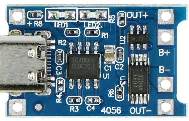
The TP4056, manufactured by Makers (Part ID: TP4036), is a lithium-ion battery charger IC designed for single-cell lithium-ion batteries. It provides a constant current/constant voltage (CC/CV) charging profile, ensuring safe and efficient charging. The TP4056 is widely used in battery-powered devices due to its compact size, high efficiency, and integrated safety features such as over-voltage protection, under-voltage lockout, and thermal regulation.
Explore Projects Built with TP4056


Explore Projects Built with TP4056
Common Applications and Use Cases
- Charging single-cell lithium-ion or lithium-polymer batteries
- Power banks and portable chargers
- Wearable devices and IoT gadgets
- DIY electronics projects
- Battery management systems (BMS)
Technical Specifications
The TP4056 is a versatile and reliable charging IC with the following key specifications:
| Parameter | Value |
|---|---|
| Input Voltage Range | 4.0V to 8.0V |
| Charging Voltage | 4.2V ± 1% |
| Maximum Charging Current | 1A (adjustable via external resistor) |
| Charging Method | Constant Current/Constant Voltage (CC/CV) |
| Operating Temperature Range | -40°C to +85°C |
| Standby Current | < 55µA |
| Thermal Regulation | 120°C (automatic current reduction) |
| Protection Features | Over-voltage, under-voltage lockout, thermal regulation |
Pin Configuration and Descriptions
The TP4056 IC is typically available in an 8-pin SOP package. Below is the pin configuration and description:
| Pin Number | Pin Name | Description |
|---|---|---|
| 1 | TEMP | Temperature sense input. Connect to an NTC thermistor for battery temperature monitoring. |
| 2 | PROG | Programs the charging current via an external resistor. |
| 3 | GND | Ground connection. |
| 4 | VCC | Input supply voltage (4.0V to 8.0V). |
| 5 | BAT | Battery connection pin. Connect directly to the positive terminal of the battery. |
| 6 | STDBY | Open-drain status output. Indicates charging status (low = charging, high = standby). |
| 7 | CHRG | Open-drain status output. Indicates charging in progress (low = charging). |
| 8 | CE | Chip enable. Active low. Pull low to enable the IC, or high to disable it. |
Usage Instructions
How to Use the TP4056 in a Circuit
- Power Supply: Connect a DC power source (e.g., USB 5V) to the VCC pin. Ensure the input voltage is within the range of 4.0V to 8.0V.
- Battery Connection: Connect the positive terminal of the lithium-ion battery to the BAT pin and the negative terminal to GND.
- Programming Charging Current: Use an external resistor (RPROG) connected to the PROG pin to set the desired charging current. The charging current can be calculated using the formula: [ I_{CHG} = \frac{1200}{R_{PROG}} ] For example, a 1.2kΩ resistor sets the charging current to 1A.
- Status Indicators: Use the CHRG and STDBY pins to monitor the charging status. These pins can be connected to LEDs for visual indication.
- Temperature Monitoring: Connect an NTC thermistor to the TEMP pin for battery temperature monitoring. If not used, connect TEMP to GND.
Important Considerations and Best Practices
- Thermal Management: Ensure proper heat dissipation by using a PCB with adequate thermal vias and copper area around the IC.
- Battery Protection: Use a protection circuit module (PCM) with the battery to prevent over-discharge and over-current conditions.
- Input Voltage: Avoid exceeding the maximum input voltage of 8.0V to prevent damage to the IC.
- Current Limiting: Select the RPROG resistor carefully to avoid overcharging the battery.
Example: Using TP4056 with Arduino UNO
The TP4056 can be used in conjunction with an Arduino UNO to monitor the charging status. Below is an example code snippet:
// TP4056 Charging Status Monitoring with Arduino UNO
// Connect CHRG pin to Arduino pin 2 and STDBY pin to Arduino pin 3

const int chrgPin = 2;  // CHRG pin of TP4056
const int stdbyPin = 3; // STDBY pin of TP4056

void setup() {
  pinMode(chrgPin, INPUT);  // Set CHRG pin as input
  pinMode(stdbyPin, INPUT); // Set STDBY pin as input
  Serial.begin(9600);       // Initialize serial communication
}

void loop() {
  int chrgStatus = digitalRead(chrgPin);  // Read CHRG pin status
  int stdbyStatus = digitalRead(stdbyPin); // Read STDBY pin status

  if (chrgStatus == LOW) {
    Serial.println("Battery is charging...");
  } else if (stdbyStatus == HIGH) {
    Serial.println("Battery is fully charged or no battery connected.");
  } else {
    Serial.println("Unknown status.");
  }

  delay(1000); // Wait for 1 second before checking again
}
Troubleshooting and FAQs
Common Issues and Solutions
Battery Not Charging
- Cause: Incorrect input voltage or loose connections.
- Solution: Verify that the input voltage is between 4.0V and 8.0V. Check all connections.
Overheating
- Cause: Excessive charging current or insufficient heat dissipation.
- Solution: Reduce the charging current by increasing the RPROG resistor value. Ensure proper PCB design for heat dissipation.
CHRG and STDBY LEDs Not Working
- Cause: Incorrect wiring or damaged LEDs.
- Solution: Check the connections to the CHRG and STDBY pins. Replace faulty LEDs if necessary.
Battery Overcharging
- Cause: Faulty IC or incorrect RPROG resistor value.
- Solution: Verify the RPROG resistor value and replace the IC if needed.
FAQs
Q1: Can the TP4056 charge multiple batteries in series?
A1: No, the TP4056 is designed for single-cell lithium-ion batteries only. Charging multiple cells in series requires a dedicated multi-cell charger IC.
Q2: What happens if the input voltage exceeds 8.0V?
A2: Exceeding the maximum input voltage can damage the IC. Always ensure the input voltage is within the specified range.
Q3: Can I use the TP4056 without a thermistor?
A3: Yes, if temperature monitoring is not required, connect the TEMP pin to GND.
Q4: How do I adjust the charging current?
A4: The charging current is set using an external resistor (RPROG). Use the formula ( I_{CHG} = \frac{1200}{R_{PROG}} ) to calculate the resistor value.
By following this documentation, users can effectively integrate the TP4056 into their projects for safe and efficient battery charging.