How to Use Sabertooth 2*32: Examples, Pinouts, and Specs
Introduction
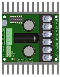
The Sabertooth 2*32 is a dual-channel motor driver designed to control two DC motors with a maximum continuous current of 32A per channel. Manufactured by Dimension Engineering, this motor driver is highly versatile and suitable for a wide range of applications, including robotics, automation systems, and remote-controlled vehicles. It supports multiple control modes such as analog, R/C, serial, and packetized serial, making it adaptable to various control systems.
Explore Projects Built with Sabertooth 2*32
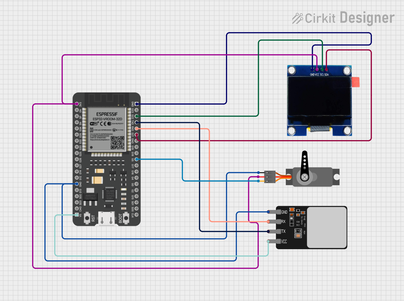
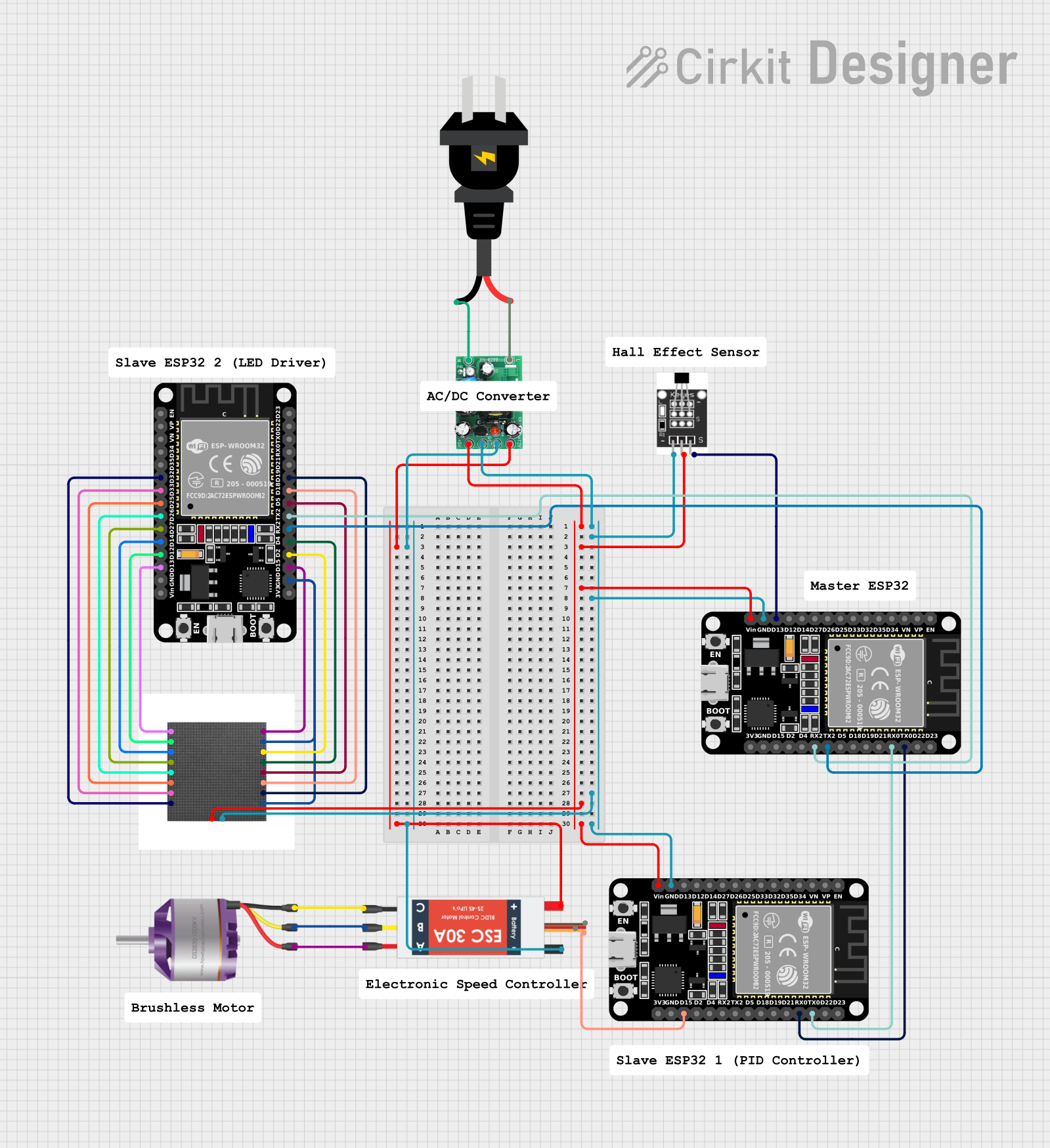
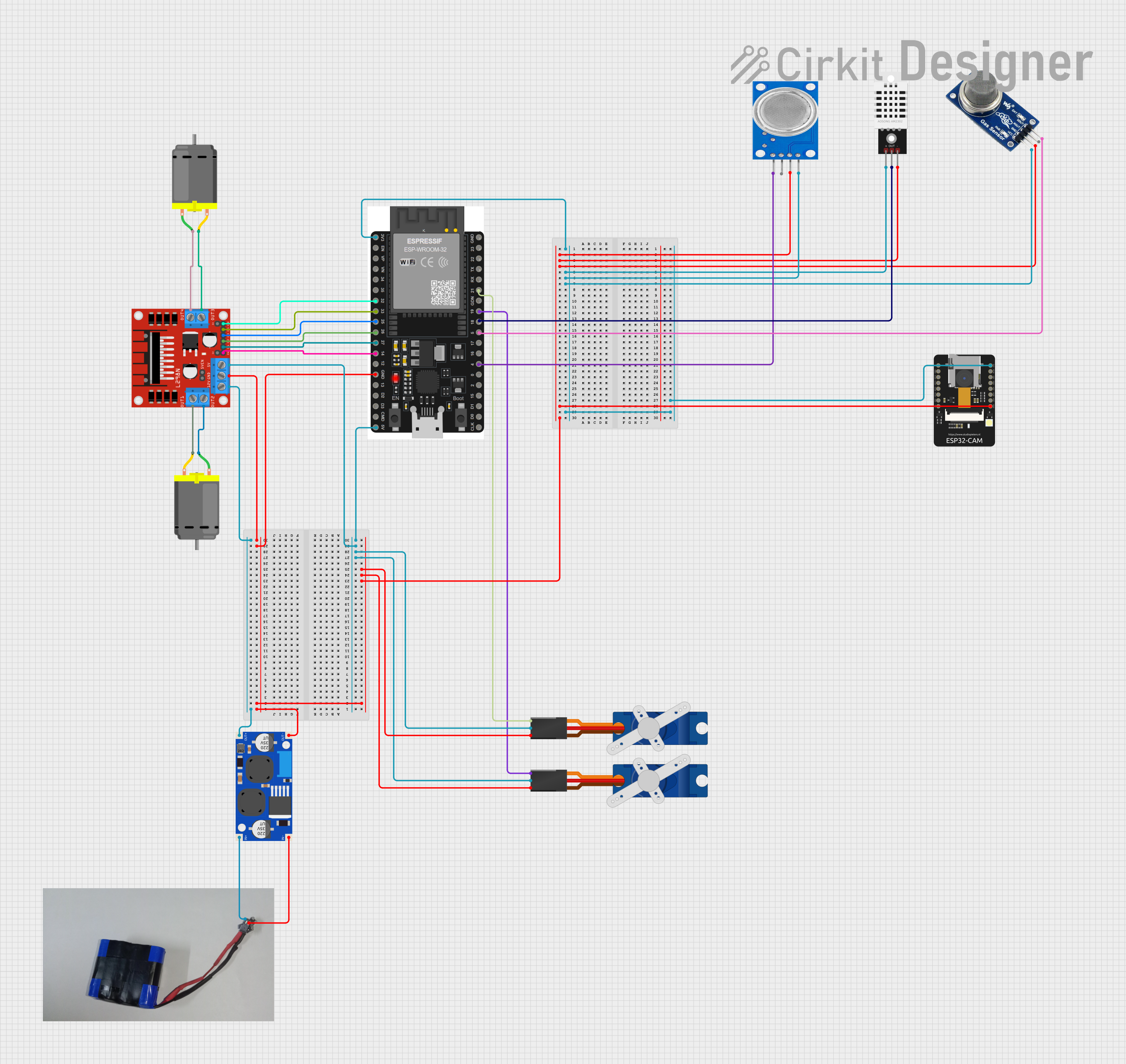
Explore Projects Built with Sabertooth 2*32
Common Applications
- Robotics (e.g., mobile robots, robotic arms)
- Automated guided vehicles (AGVs)
- Remote-controlled cars, boats, and drones
- Conveyor systems and industrial automation
- Electric wheelchairs and mobility devices
Technical Specifications
The following table outlines the key technical details of the Sabertooth 2*32 motor driver:
| Parameter | Value |
|---|---|
| Input Voltage Range | 6V to 30V |
| Continuous Current (per channel) | 32A |
| Peak Current (per channel) | 64A (for a few seconds) |
| Control Modes | Analog, R/C, Serial, Packetized Serial |
| Operating Temperature Range | -40°C to +85°C |
| Dimensions | 3.25" x 2.75" x 1.5" (82.5mm x 70mm x 38mm) |
| Weight | 150g |
| Communication Protocols | TTL Serial, USB (via adapter) |
| Safety Features | Overcurrent, overvoltage, thermal protection |
Pin Configuration and Descriptions
The Sabertooth 2*32 has a set of input and output pins for motor control and communication. Below is the pin configuration:
| Pin Name | Type | Description |
|---|---|---|
| M1A, M1B | Motor Output | Connect to the terminals of Motor 1. |
| M2A, M2B | Motor Output | Connect to the terminals of Motor 2. |
| VIN, GND | Power Input | Connect to the power supply (6V to 30V) and ground. |
| S1, S2 | Signal Input | Control inputs for analog, R/C, or serial modes. |
| 0V, 5V | Power Output | Provides 5V regulated output for external devices (e.g., sensors, microcontrollers). |
| TX, RX | Serial I/O | TTL serial communication pins for interfacing with microcontrollers or PCs. |
| USB | Communication | USB port for configuration and control (requires USB-to-serial adapter). |
Usage Instructions
Connecting the Sabertooth 2*32
- Power Supply: Connect a DC power supply (6V to 30V) to the VIN and GND terminals. Ensure the power supply can handle the current requirements of your motors.
- Motor Connections: Connect the terminals of Motor 1 to M1A and M1B, and Motor 2 to M2A and M2B.
- Control Input: Depending on your control mode:
- For analog control, connect a potentiometer or analog signal to S1 and S2.
- For R/C control, connect the R/C receiver outputs to S1 and S2.
- For serial control, connect the TX and RX pins to a microcontroller or PC.
- Configuration: Use the DIP switches on the board to set the operating mode. Refer to the user manual for DIP switch settings.
Example: Using with Arduino UNO
The Sabertooth 2*32 can be controlled via serial communication with an Arduino UNO. Below is an example code snippet to control two motors:
#include <SoftwareSerial.h>

// Define TX and RX pins for SoftwareSerial
SoftwareSerial SabertoothSerial(10, 11); // TX = Pin 10, RX = Pin 11

void setup() {
  SabertoothSerial.begin(9600); // Initialize serial communication at 9600 baud
}

void loop() {
  // Send commands to control motor speed
  // Motor 1 forward at 50% speed
  SabertoothSerial.write(64 + 50); // 64 is the base command for motor 1 forward

  delay(1000); // Run motor for 1 second

  // Motor 2 reverse at 75% speed
  SabertoothSerial.write(192 + 75); // 192 is the base command for motor 2 reverse

  delay(1000); // Run motor for 1 second
}
Important Considerations
- Power Supply: Ensure the power supply voltage and current ratings match the requirements of your motors and the Sabertooth 2*32.
- Heat Dissipation: The motor driver may heat up during operation. Use proper ventilation or a heatsink if necessary.
- Wiring: Use thick wires for motor and power connections to handle high currents without overheating.
- Configuration: Always configure the DIP switches correctly before powering the device.
Troubleshooting and FAQs
Common Issues and Solutions
Motors not running:
- Check the power supply voltage and connections.
- Verify the DIP switch settings for the selected control mode.
- Ensure the control signals (e.g., serial commands) are being sent correctly.
Overheating:
- Ensure the motor driver is not exceeding its current or voltage limits.
- Improve ventilation or add a heatsink to the device.
Erratic motor behavior:
- Check for loose or faulty wiring.
- Verify that the control signals are clean and within the expected range.
No response to serial commands:
- Ensure the baud rate matches the Sabertooth 2*32 settings.
- Check the TX and RX connections between the microcontroller and the motor driver.
FAQs
Q: Can I use the Sabertooth 2*32 with a 24V battery?
A: Yes, the Sabertooth 2*32 supports input voltages up to 30V, so a 24V battery is within the acceptable range.
Q: How do I reset the Sabertooth 2*32 to factory settings?
A: You can reset the device by setting all DIP switches to the default position and cycling the power.
Q: Can I control brushless motors with the Sabertooth 2*32?
A: No, the Sabertooth 2*32 is designed for brushed DC motors only.
Q: Is it possible to control the Sabertooth 2*32 via USB?
A: Yes, but you will need a USB-to-serial adapter to connect it to a PC.
By following this documentation, you can effectively integrate the Sabertooth 2*32 into your projects and troubleshoot common issues.