How to Use Expansion board : Examples, Pinouts, and Specs
Introduction
The Yahboom STM8S003F3U6TR Expansion Board is a versatile circuit board designed to enhance the functionality of a primary circuit board. It provides additional connections and interfaces, enabling the integration of extra components or modules. This expansion board is particularly useful in prototyping, educational projects, and applications requiring modularity and scalability.
Explore Projects Built with Expansion board

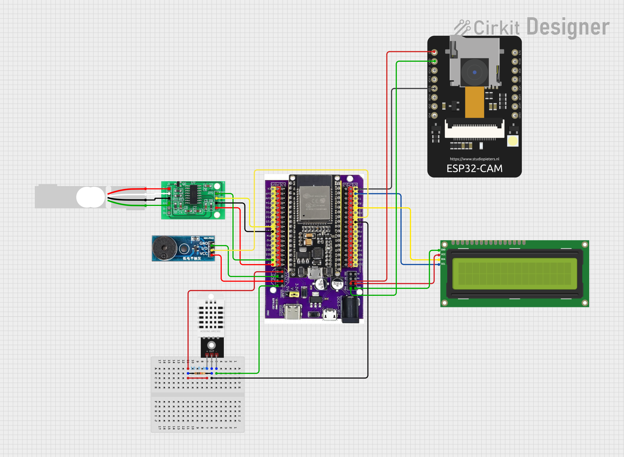
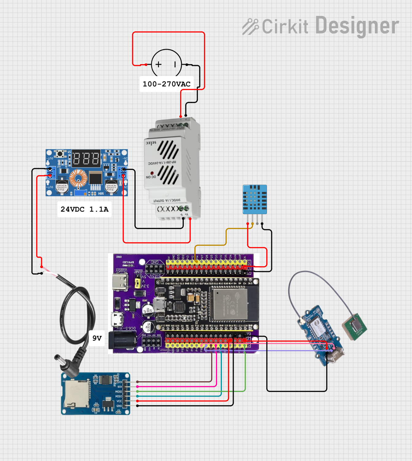

Explore Projects Built with Expansion board
Common Applications and Use Cases
- Robotics and automation projects
- IoT (Internet of Things) device prototyping
- Educational electronics and STEM learning
- Adding sensors, actuators, or communication modules to microcontroller systems
- Extending the capabilities of development boards like Arduino or Raspberry Pi
Technical Specifications
The Yahboom STM8S003F3U6TR Expansion Board is built around the STM8S003F3U6TR microcontroller, offering reliable performance and a range of features. Below are the key technical details:
Key Technical Details
- Microcontroller: STM8S003F3U6TR
- Operating Voltage: 2.95V to 5.5V
- Maximum Current: 20mA per I/O pin
- Clock Speed: 16 MHz
- Flash Memory: 8 KB
- RAM: 1 KB
- EEPROM: 128 bytes
- Communication Interfaces: UART, I2C, SPI
- GPIO Pins: Up to 16 configurable pins
- Dimensions: Varies based on the specific board design
- Operating Temperature: -40°C to +85°C
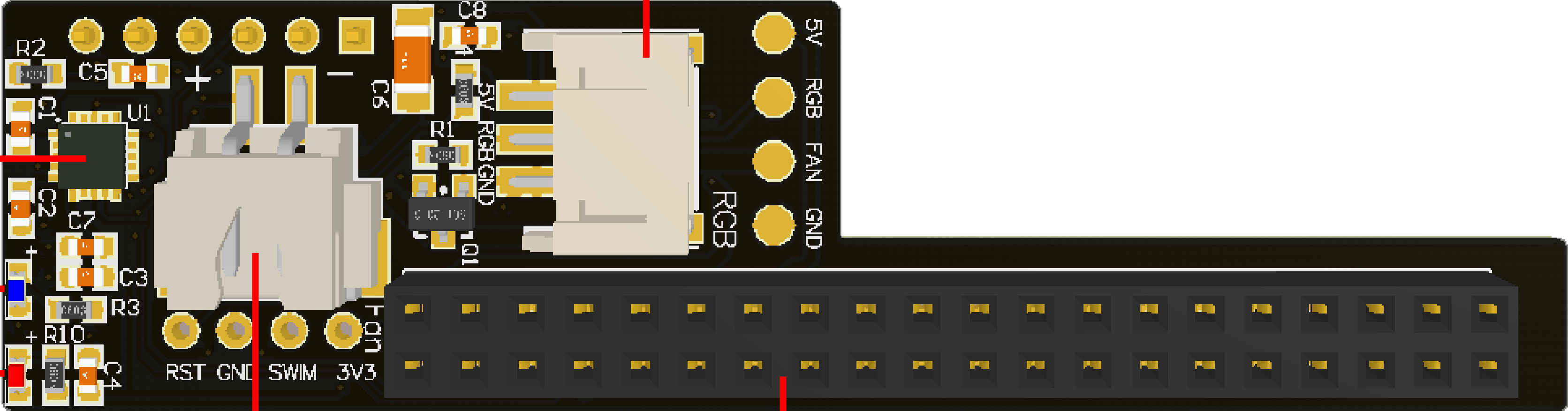
Pin Configuration and Descriptions
The pinout of the expansion board is as follows:
| Pin Name | Type | Description |
|---|---|---|
| VCC | Power Input | Power supply input (2.95V to 5.5V) |
| GND | Ground | Ground connection |
| GPIO1-GPIO16 | Digital I/O | General-purpose input/output pins |
| TX | UART TX | UART transmit pin for serial communication |
| RX | UART RX | UART receive pin for serial communication |
| SCL | I2C Clock | I2C clock line for communication |
| SDA | I2C Data | I2C data line for communication |
| MOSI | SPI Data Out | SPI Master Out Slave In |
| MISO | SPI Data In | SPI Master In Slave Out |
| SCK | SPI Clock | SPI clock line |
| RESET | Reset | Resets the microcontroller |
| ADC1-ADC4 | Analog Input | Analog-to-digital converter inputs |
Usage Instructions
How to Use the Expansion Board in a Circuit
- Power the Board: Connect the VCC and GND pins to a suitable power source within the operating voltage range (2.95V to 5.5V).
- Connect to a Microcontroller: Use the appropriate communication interface (UART, I2C, or SPI) to connect the expansion board to your primary microcontroller or development board.
- Configure GPIO Pins: Set the GPIO pins as input or output based on your application requirements.
- Add Peripherals: Attach sensors, actuators, or other modules to the expansion board using the available pins.
- Program the Microcontroller: Write and upload code to the primary microcontroller to control the expansion board and connected peripherals.
Important Considerations and Best Practices
- Ensure the power supply voltage matches the board's operating range to avoid damage.
- Use pull-up or pull-down resistors for GPIO pins if required by your circuit design.
- Avoid exceeding the maximum current rating (20mA) for any I/O pin.
- Properly terminate unused pins to prevent floating inputs, which can cause erratic behavior.
- Use decoupling capacitors near the power pins to reduce noise and improve stability.
Example Code for Arduino UNO
Below is an example of how to interface the expansion board with an Arduino UNO using I2C communication:
#include <Wire.h> // Include the Wire library for I2C communication

#define DEVICE_ADDRESS 0x20 // Replace with the I2C address of your expansion board

void setup() {
  Wire.begin(); // Initialize I2C communication
  Serial.begin(9600); // Start serial communication for debugging

  // Send initialization command to the expansion board
  Wire.beginTransmission(DEVICE_ADDRESS);
  Wire.write(0x01); // Example command to initialize the board
  Wire.endTransmission();

  Serial.println("Expansion board initialized.");
}

void loop() {
  // Example: Read data from the expansion board
  Wire.requestFrom(DEVICE_ADDRESS, 1); // Request 1 byte of data
  if (Wire.available()) {
    int data = Wire.read(); // Read the received byte
    Serial.print("Received data: ");
    Serial.println(data);
  }

  delay(1000); // Wait for 1 second before the next read
}
Troubleshooting and FAQs
Common Issues and Solutions
The board is not powering on:
- Verify that the power supply voltage is within the specified range (2.95V to 5.5V).
- Check the connections to the VCC and GND pins.
Communication with the board is not working:
- Ensure the correct communication protocol (UART, I2C, or SPI) is being used.
- Double-check the wiring and pin connections.
- Verify the device address if using I2C.
GPIO pins are not functioning as expected:
- Confirm that the pins are configured correctly as input or output in your code.
- Check for any short circuits or incorrect connections.
Erratic behavior or instability:
- Add decoupling capacitors near the power pins to reduce noise.
- Ensure unused pins are properly terminated.
FAQs
Q: Can this expansion board be used with Raspberry Pi?
A: Yes, the expansion board can be interfaced with Raspberry Pi using I2C, SPI, or UART communication protocols.
Q: What is the maximum current the board can handle?
A: Each GPIO pin can handle a maximum current of 20mA. Ensure not to exceed this limit to avoid damage.
Q: How do I find the I2C address of the board?
A: Use an I2C scanner sketch on your microcontroller to detect the board's I2C address.
Q: Can I use this board in outdoor environments?
A: The board operates within a temperature range of -40°C to +85°C. However, ensure it is protected from moisture and extreme environmental conditions.