How to Use LM2596: Examples, Pinouts, and Specs
Introduction
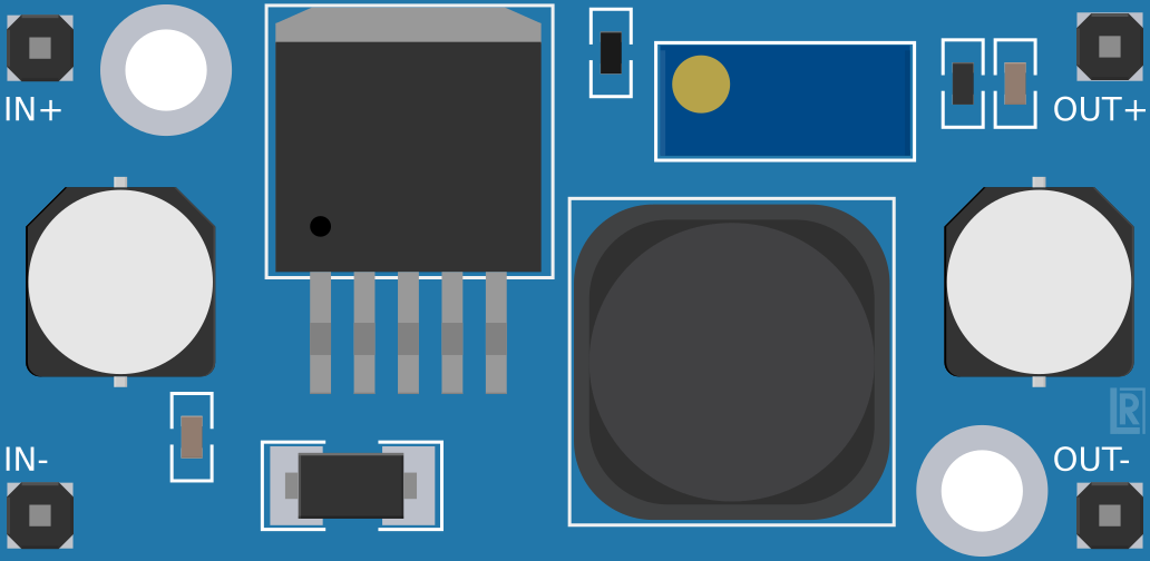
The LM2596 is a step-down (buck) voltage regulator designed to efficiently convert a higher input voltage into a stable, regulated output voltage. It is capable of delivering up to 3A of output current, making it ideal for powering a wide range of electronic devices. With its wide input voltage range (4.5V to 40V) and adjustable or fixed output voltage options, the LM2596 is a versatile component for power management in various applications.
Explore Projects Built with LM2596


Explore Projects Built with LM2596
Common Applications and Use Cases
- Power supply circuits for microcontrollers, sensors, and modules
- Battery-powered devices requiring efficient voltage regulation
- DC-DC converters in industrial and automotive systems
- LED drivers and portable electronics
- Voltage regulation in DIY electronics projects
Technical Specifications
The LM2596 is available in both adjustable and fixed output voltage versions. Below are the key technical details:
General Specifications
| Parameter | Value |
|---|---|
| Input Voltage Range | 4.5V to 40V |
| Output Voltage Range | 1.23V to 37V (adjustable) |
| Fixed Output Voltages | 3.3V, 5V, 12V |
| Maximum Output Current | 3A |
| Efficiency | Up to 90% |
| Switching Frequency | 150 kHz |
| Operating Temperature | -40°C to +125°C |
| Package Type | TO-220, TO-263 (D2PAK) |
Pin Configuration and Descriptions
The LM2596 typically comes in a 5-pin TO-220 or TO-263 package. Below is the pinout description:
| Pin Number | Pin Name | Description |
|---|---|---|
| 1 | VIN | Input voltage pin. Connect to the unregulated DC input voltage. |
| 2 | Output | Regulated output voltage pin. Connect to the load. |
| 3 | Ground | Ground pin. Connect to the circuit ground. |
| 4 | Feedback | Feedback pin. Used to set the output voltage (for adjustable versions). |
| 5 | ON/OFF | Enable pin. Pull low to disable the regulator; leave open or pull high to enable. |
Usage Instructions
How to Use the LM2596 in a Circuit
- Input Voltage: Connect the input voltage (4.5V to 40V) to the VIN pin. Ensure the input voltage is higher than the desired output voltage by at least 1.5V for proper regulation.
- Output Voltage: For fixed versions, the output voltage is pre-set (e.g., 5V). For adjustable versions, connect a resistor divider to the Feedback pin to set the desired output voltage.
- Capacitors: Place input and output capacitors close to the regulator to ensure stability and reduce noise. Typical values are:
- Input capacitor: 100 µF electrolytic
- Output capacitor: 220 µF electrolytic
- Inductor: Use an appropriate inductor value (e.g., 33 µH) based on the desired output voltage and current.
- Enable Pin: If using the ON/OFF pin, connect it to ground to disable the regulator or leave it open/pull high to enable it.
Example Circuit
Below is a basic circuit for an adjustable LM2596 regulator:
VIN (12V) ----+---- Input Capacitor (100 µF) ---- VIN (Pin 1)
              |
              +---- Inductor (33 µH) ---- Output (Pin 2) ---- VOUT
              |
              +---- Ground (Pin 3)
Arduino Example Code
The LM2596 can be used to power an Arduino UNO. Here's an example of how to monitor the output voltage using the Arduino's ADC:
// Define the analog pin connected to the LM2596 output
const int voltagePin = A0;

// Reference voltage for the ADC (5V for Arduino UNO)
const float referenceVoltage = 5.0;

// Voltage divider resistors (if used to scale down the LM2596 output voltage)
const float R1 = 10000.0; // Resistor connected to VOUT
const float R2 = 1000.0;  // Resistor connected to ground

void setup() {
  Serial.begin(9600); // Initialize serial communication
}

void loop() {
  int adcValue = analogRead(voltagePin); // Read the ADC value
  float voltage = (adcValue / 1023.0) * referenceVoltage; // Convert to voltage

  // If a voltage divider is used, scale the voltage accordingly
  voltage = voltage * ((R1 + R2) / R2);

  // Print the measured voltage
  Serial.print("Output Voltage: ");
  Serial.print(voltage);
  Serial.println(" V");

  delay(1000); // Wait for 1 second before the next reading
}
Important Considerations and Best Practices
- Heat Dissipation: The LM2596 can generate heat under high current loads. Use a heatsink or ensure proper ventilation to prevent overheating.
- Input Voltage: Ensure the input voltage is within the specified range and sufficiently higher than the desired output voltage.
- Component Selection: Choose appropriate capacitors and inductors based on the output voltage and current requirements.
- PCB Layout: Minimize the trace lengths for the input and output connections to reduce noise and improve stability.
Troubleshooting and FAQs
Common Issues and Solutions
Output Voltage is Unstable or Noisy
- Ensure proper placement of input and output capacitors close to the regulator.
- Use low-ESR capacitors to improve stability.
- Check for loose connections or poor solder joints.
Regulator Overheating
- Verify that the input voltage is within the specified range.
- Use a heatsink or improve airflow around the regulator.
- Reduce the load current if it exceeds 3A.
No Output Voltage
- Check the ON/OFF pin. Ensure it is not pulled low.
- Verify the input voltage and connections.
- Inspect the feedback resistor network (for adjustable versions).
FAQs
Q: Can the LM2596 be used with a battery as the input source?
A: Yes, the LM2596 can be used with a battery as long as the input voltage is within the specified range (4.5V to 40V).
Q: What is the efficiency of the LM2596?
A: The LM2596 can achieve up to 90% efficiency, depending on the input voltage, output voltage, and load current.
Q: Can I use the LM2596 to power an Arduino UNO?
A: Yes, the LM2596 is suitable for powering an Arduino UNO. Ensure the output voltage is set to 5V and the input voltage is within the regulator's range.
Q: How do I calculate the output voltage for the adjustable version?
A: Use the formula:
[
V_{OUT} = V_{REF} \times \left(1 + \frac{R1}{R2}\right)
]
where ( V_{REF} ) is 1.23V, and ( R1 ) and ( R2 ) are the feedback resistors.
By following this documentation, you can effectively integrate the LM2596 into your projects and troubleshoot common issues.