How to Use CD4046B: Examples, Pinouts, and Specs

 Design with CD4046B in Cirkit Designer
Introduction
The CD4046B is a versatile micropower phase-locked loop (PLL) integrated circuit (IC) designed and manufactured by Texas Instruments. This electronic component is essential in various applications, including communication systems, frequency modulation/demodulation, and signal synchronization. The PLL consists of a linear voltage-controlled oscillator (VCO) and two different phase comparators with a common signal input amplifier and a common comparator input. A programmable reference frequency divider is also included, allowing for a wide range of uses in frequency synthesis and control applications.
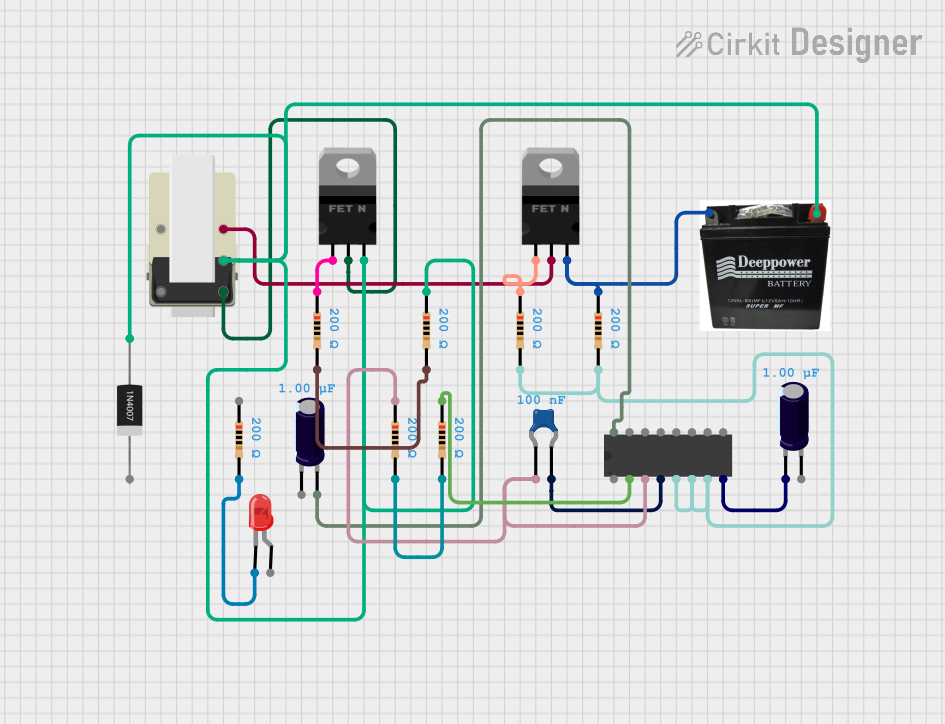
Explore Projects Built with CD4046B

 Open Project in Cirkit Designer
 Open Project in Cirkit Designer
 Open Project in Cirkit Designer
 Open Project in Cirkit Designer
Explore Projects Built with CD4046B

 Open Project in Cirkit Designer
 Open Project in Cirkit Designer
 Open Project in Cirkit Designer
 Open Project in Cirkit Designer
Common Applications
- Frequency synthesis and multiplication
- Frequency modulation and demodulation
- Signal synchronization and phase detection
- Clock recovery in digital communication systems
- Motor speed control
Technical Specifications
Key Technical Details
- Supply Voltage (Vdd): 3V to 18V
- Input Frequency (Fin): 1Hz to 10MHz (varies with Vdd)
- VCO Frequency Range: 10Hz to 3MHz (varies with Vdd)
- Operating Temperature Range: -55°C to +125°C
- Package Types: DIP, SOIC
Pin Configuration and Descriptions
| Pin Number | Name | Description |
|---|---|---|
| 1 | PC1 | Phase Comparator I output |
| 2 | PC2 | Phase Comparator II output |
| 3 | ZC | Zero Crossing Detector output |
| 4 | VCO IN | VCO input |
| 5 | VCO OUT | VCO output |
| 6 | VCO CAP | External capacitor for VCO |
| 7 | VCO RES | External resistor for VCO |
| 8 | GND | Ground (0V) |
| 9 | INH | Inhibit input (active high) |
| 10 | SIG IN | Signal input |
| 11 | SIG OUT | Signal output |
| 12 | R1 | Reference Divider input |
| 13 | R2 | Reference Divider output |
| 14 | Vdd | Positive supply voltage |
| 15 | OSC OUT | Oscillator output |
| 16 | OSC IN | Oscillator input |
Usage Instructions
How to Use the CD4046B in a Circuit
Power Supply: Connect the Vdd pin to a DC power supply within the range of 3V to 18V. Ensure that the GND pin is connected to the system ground.
VCO Configuration: Attach an external capacitor to the VCO CAP pin and an external resistor to the VCO RES pin to set the desired VCO frequency range.
Signal Input: Apply the input signal to the SIG IN pin for frequency comparison. The signal frequency should be within the specified input frequency range.
Phase Comparator: Choose the appropriate phase comparator (PC1 or PC2) for your application and connect it to the relevant circuitry.
Frequency Divider: If a frequency division is required, connect a programmable divider or counter to the R1 and R2 pins.
Output: Utilize the VCO OUT, PC1, or PC2 outputs as needed for your application.
Important Considerations and Best Practices
- Ensure that the power supply voltage does not exceed the maximum rating to prevent damage to the IC.
- Use decoupling capacitors close to the power supply pins to minimize noise and voltage spikes.
- Keep signal lines as short as possible to reduce the risk of noise interference.
- When using the VCO, select the external resistor and capacitor values carefully to achieve the desired frequency stability and range.
Troubleshooting and FAQs
Common Issues
- Unstable VCO Frequency: Check the external resistor and capacitor values. Ensure they are within the recommended range for stability.
- No Output Signal: Verify that the power supply is within the specified range and that all connections are secure.
- Incorrect Phase Comparator Output: Ensure that the input signals are within the frequency range and that the phase comparator is correctly configured for the application.
Solutions and Tips
- If the VCO frequency is unstable, consider using higher-quality components with tighter tolerances for the external resistor and capacitor.
- Double-check the pin connections against the pin configuration table to ensure accuracy.
- Use an oscilloscope to monitor the VCO and phase comparator outputs for troubleshooting.
FAQs
Q: Can the CD4046B be used for high-frequency applications? A: The CD4046B is suitable for applications up to 10MHz, but the actual frequency limit depends on the supply voltage and external components.
Q: Is it possible to use the CD4046B for amplitude modulation? A: While the CD4046B is primarily designed for frequency modulation and phase-locked loop applications, with additional circuitry, it can be adapted for amplitude modulation tasks.
Q: How do I set the VCO frequency range? A: The VCO frequency is set by choosing the correct values for the external resistor and capacitor connected to the VCO RES and VCO CAP pins, respectively.
Example Code for Arduino UNO
Below is an example code snippet for interfacing the CD4046B with an Arduino UNO to monitor the VCO frequency. This example assumes you have connected the VCO OUT pin to a digital input on the Arduino.
// Define the pin connected to the VCO OUT
const int vcoOutPin = 2;

void setup() {
  // Initialize the serial communication
  Serial.begin(9600);
  // Set the VCO OUT pin as an input
  pinMode(vcoOutPin, INPUT);
}

void loop() {
  // Read the frequency from the VCO OUT pin
  int frequency = pulseIn(vcoOutPin, HIGH);
  // Convert the reading to an actual frequency value (depends on your specific setup)
  float actualFrequency = convertToFrequency(frequency);
  // Print the frequency to the serial monitor
  Serial.println(actualFrequency);
}

float convertToFrequency(int pulseLength) {
  // This function converts pulse length to frequency.
  // The conversion formula will depend on the specific setup and external components used.
  // For example purposes, we assume a direct correlation (1:1).
  return 1.0 / (pulseLength * 0.000001); // Convert microseconds to seconds and invert
}
Remember to adjust the convertToFrequency function based on the actual VCO frequency range and the external components you have used. This code is for demonstration purposes and may require modifications to work with your specific application.