
How to Use STM32 Nucleo boards: Examples, Pinouts, and Specs
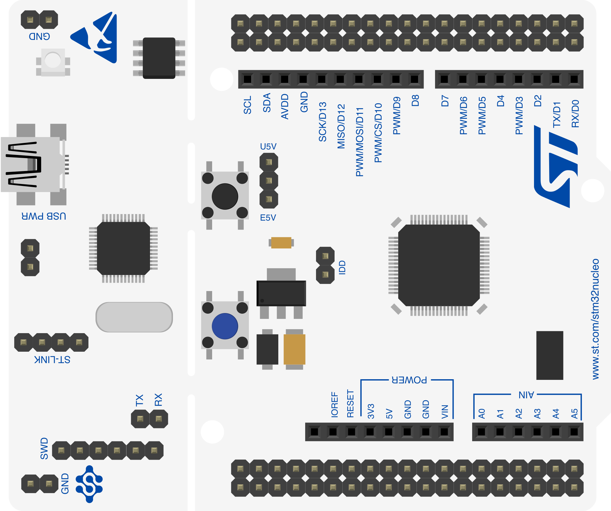
 Design with STM32 Nucleo boards in Cirkit Designer
Introduction
STM32 Nucleo boards are development platforms designed to simplify prototyping and application development using STM32 microcontrollers. These boards provide a versatile environment for developers, offering a range of connectivity options, compatibility with Arduino shields, and support for various software development tools such as STM32CubeIDE, Keil, and IAR Embedded Workbench.
Common applications of STM32 Nucleo boards include:
- IoT device prototyping
- Embedded system development
- Robotics and automation projects
- Sensor interfacing and data acquisition
- Educational purposes for learning microcontroller programming
Explore Projects Built with STM32 Nucleo boards
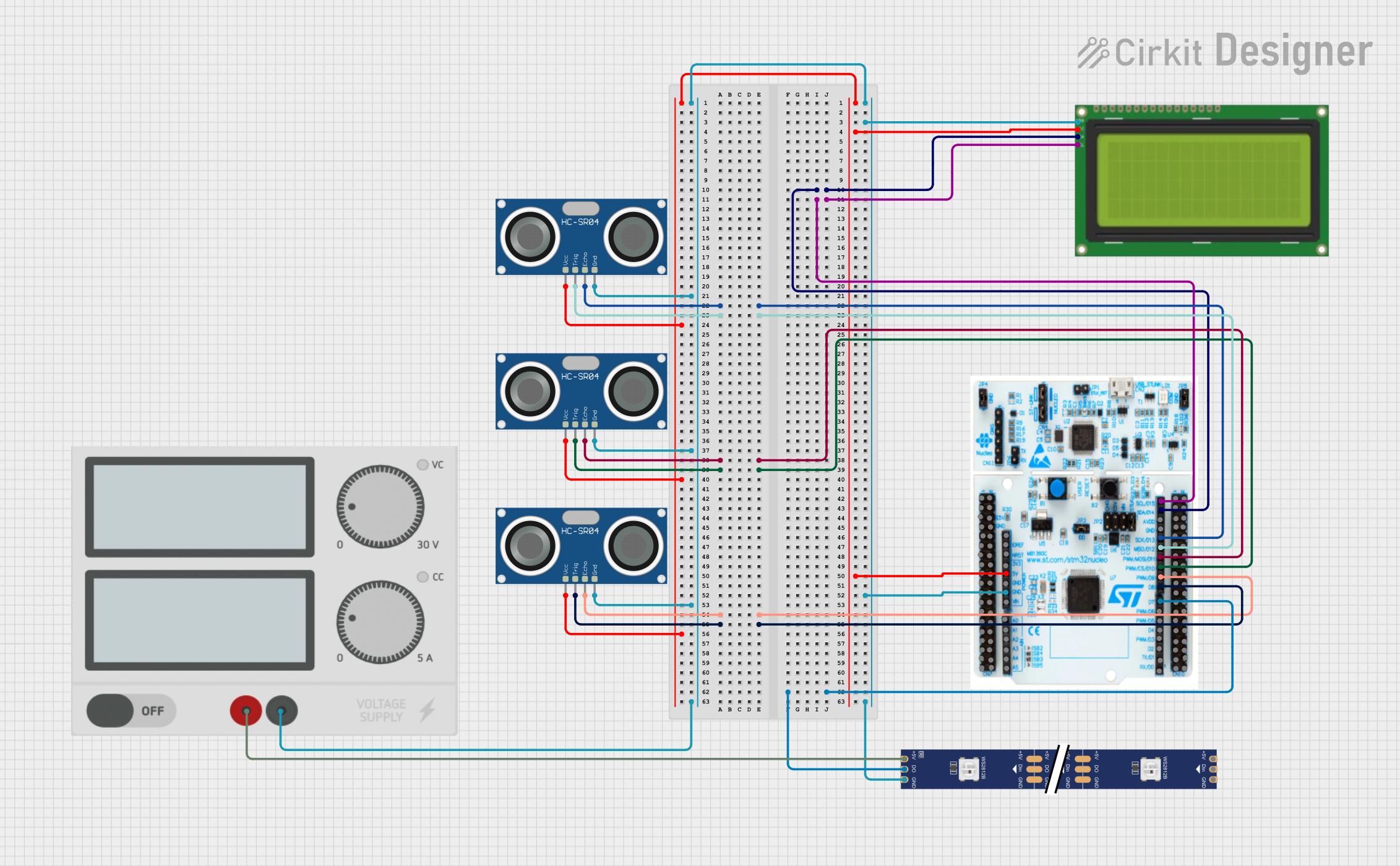 Open Project in Cirkit Designer
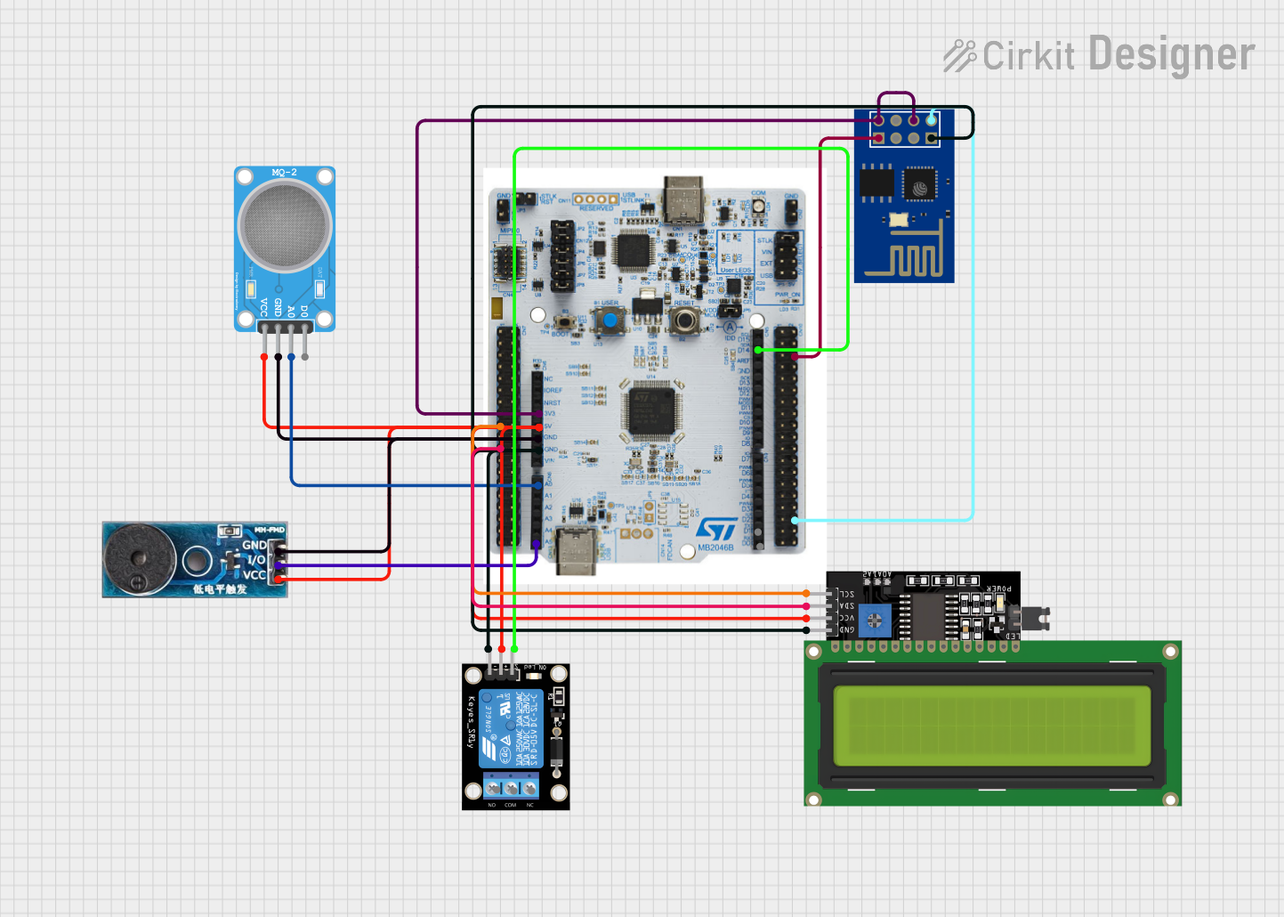 Open Project in Cirkit Designer
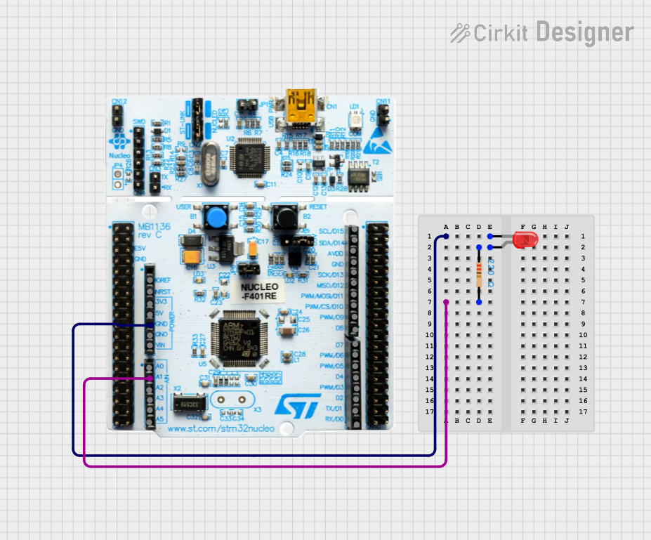 Open Project in Cirkit Designer
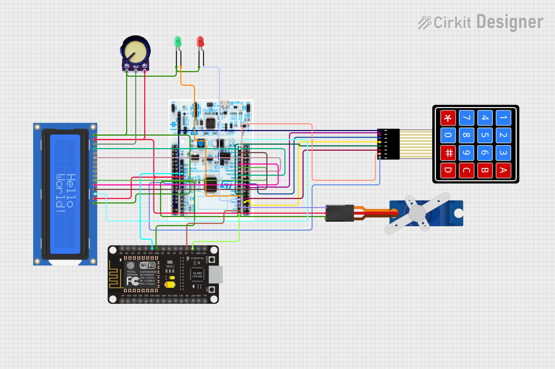 Open Project in Cirkit Designer
Explore Projects Built with STM32 Nucleo boards
Open Project in Cirkit DesignerOpen Project in Cirkit DesignerOpen Project in Cirkit DesignerOpen Project in Cirkit DesignerTechnical Specifications
STM32 Nucleo boards come in various models, each featuring a specific STM32 microcontroller. Below are the general technical specifications applicable to most Nucleo boards:
Key Technical Details
- Microcontroller: STM32 family (e.g., STM32F4, STM32L4, STM32G4, etc.)
- Operating Voltage: 3.3V (logic level), 5V (power input via USB or VIN)
- Clock Speed: Up to 480 MHz (depending on the microcontroller model)
- Connectivity: USB, UART, SPI, I2C, CAN, and more
- Programming Interface: ST-LINK/V2-1 debugger/programmer onboard
- Arduino Compatibility: Supports Arduino Uno R3 pinout for shields
- Power Supply Options: USB, external VIN (7-12V), or 3.3V/5V pins
- Integrated Peripherals: GPIOs, ADCs, DACs, PWM, timers, etc.
Pin Configuration and Descriptions
The STM32 Nucleo boards feature dual-row headers for STM32 pins and Arduino-compatible headers. Below is a general pinout description:
STM32 Pin Headers
| Pin Name | Function | Description |
|---|---|---|
| PAx, PBx, etc. | GPIO, ADC, PWM, etc. | General-purpose I/O pins with alternate functions |
| VDD | Power Supply | 3.3V power output |
| GND | Ground | Common ground |
| NRST | Reset | Microcontroller reset pin |
| BOOT0 | Boot Mode Selection | Selects boot mode (e.g., flash, system memory) |
Arduino-Compatible Headers
| Pin Name | Function | Description |
|---|---|---|
| A0-A5 | Analog Input | Analog input pins |
| D0-D13 | Digital I/O | Digital input/output pins |
| VIN | Power Input | External power input (7-12V) |
| 5V | Power Output | 5V power output |
| 3.3V | Power Output | 3.3V power output |
| GND | Ground | Common ground |
Usage Instructions
How to Use the STM32 Nucleo Board in a Circuit
- Power the Board: Connect the board to your computer via a USB cable or use an external power source (VIN or 5V pin).
- Install Development Tools: Download and install STM32CubeIDE or another compatible IDE. Ensure the ST-LINK drivers are installed.
- Write and Upload Code:
- Open your IDE and create a new project for the specific STM32 microcontroller on your Nucleo board.
- Write your application code using HAL (Hardware Abstraction Layer) or LL (Low Layer) libraries.
- Compile and upload the code to the board using the ST-LINK interface.
- Connect Peripherals: Use the GPIO pins, communication interfaces (UART, SPI, I2C), or Arduino headers to connect sensors, actuators, or other peripherals.
- Debug and Test: Use the integrated ST-LINK debugger to debug your application and monitor performance.
Important Considerations and Best Practices
- Power Supply: Ensure the board is powered correctly to avoid damage. Do not exceed the voltage limits.
- Pin Configuration: Configure GPIO pins properly in your code to avoid conflicts or unintended behavior.
- Clock Settings: Set the correct clock configuration for your application in the IDE.
- Arduino Shields: Verify compatibility of Arduino shields with the STM32 Nucleo board before use.
- Static Protection: Handle the board with care to avoid damage from electrostatic discharge (ESD).
Example Code for Arduino-Compatible Usage
Below is an example of blinking an LED connected to pin D13 using STM32CubeIDE:
#include "main.h"

// Function prototypes
void SystemClock_Config(void);
static void MX_GPIO_Init(void);

int main(void) {
  // Initialize the HAL Library
  HAL_Init();

  // Configure the system clock
  SystemClock_Config();

  // Initialize GPIO
  MX_GPIO_Init();

  // Main loop
  while (1) {
    HAL_GPIO_TogglePin(GPIOA, GPIO_PIN_5); // Toggle LED on pin PA5 (D13)
    HAL_Delay(500); // Delay for 500ms
  }
}

// GPIO Initialization Function
static void MX_GPIO_Init(void) {
  GPIO_InitTypeDef GPIO_InitStruct = {0};

  // Enable GPIOA clock
  __HAL_RCC_GPIOA_CLK_ENABLE();

  // Configure GPIO pin PA5 (D13)
  GPIO_InitStruct.Pin = GPIO_PIN_5;
  GPIO_InitStruct.Mode = GPIO_MODE_OUTPUT_PP;
  GPIO_InitStruct.Pull = GPIO_NOPULL;
  GPIO_InitStruct.Speed = GPIO_SPEED_FREQ_LOW;
  HAL_GPIO_Init(GPIOA, &GPIO_InitStruct);
}

// System Clock Configuration Function
void SystemClock_Config(void) {
  // Default clock configuration (generated by STM32CubeMX)
}
Troubleshooting and FAQs
Common Issues and Solutions
Board Not Detected by IDE:
- Ensure the USB cable is functional and properly connected.
- Verify that the ST-LINK drivers are installed on your computer.
- Check if the board is powered correctly.
Code Upload Fails:
- Confirm that the correct microcontroller model is selected in the IDE.
- Ensure the ST-LINK firmware is up to date.
- Check for any hardware issues, such as loose connections.
Peripherals Not Working:
- Verify the pin configuration in your code matches the hardware setup.
- Check for proper power supply to external peripherals.
Arduino Shield Compatibility Issues:
- Ensure the shield operates at 3.3V logic levels (or use level shifters if required).
- Verify the pin mappings and functionality of the shield.
FAQs
Q: Can I use STM32 Nucleo boards with Arduino IDE?
A: Yes, STM32 Nucleo boards can be programmed using the Arduino IDE by installing the STM32 core for Arduino.
Q: How do I update the ST-LINK firmware?
A: Use the ST-LINK Utility or STM32CubeProgrammer to update the firmware. Follow the instructions provided by STMicroelectronics.
Q: Are all STM32 Nucleo boards compatible with Arduino shields?
A: Most Nucleo boards support the Arduino Uno R3 pinout, but always check the specific board's documentation for compatibility details.
Q: Can I power the board using only the USB connection?
A: Yes, the board can be powered via USB, but ensure the connected peripherals do not exceed the USB power limits.