How to Use Screen Printed Electrode: Examples, Pinouts, and Specs
Introduction
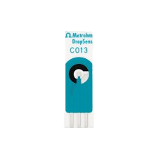
A Screen Printed Electrode (SPE) is a type of electrochemical sensor fabricated by printing conductive materials, such as carbon, silver, or gold, onto a flat substrate (e.g., ceramic or plastic). This manufacturing process enables the creation of compact, disposable, and cost-effective electrodes for a wide range of applications. SPEs are widely used in analytical chemistry, biosensing, and environmental monitoring due to their versatility and ease of use.
Explore Projects Built with Screen Printed Electrode

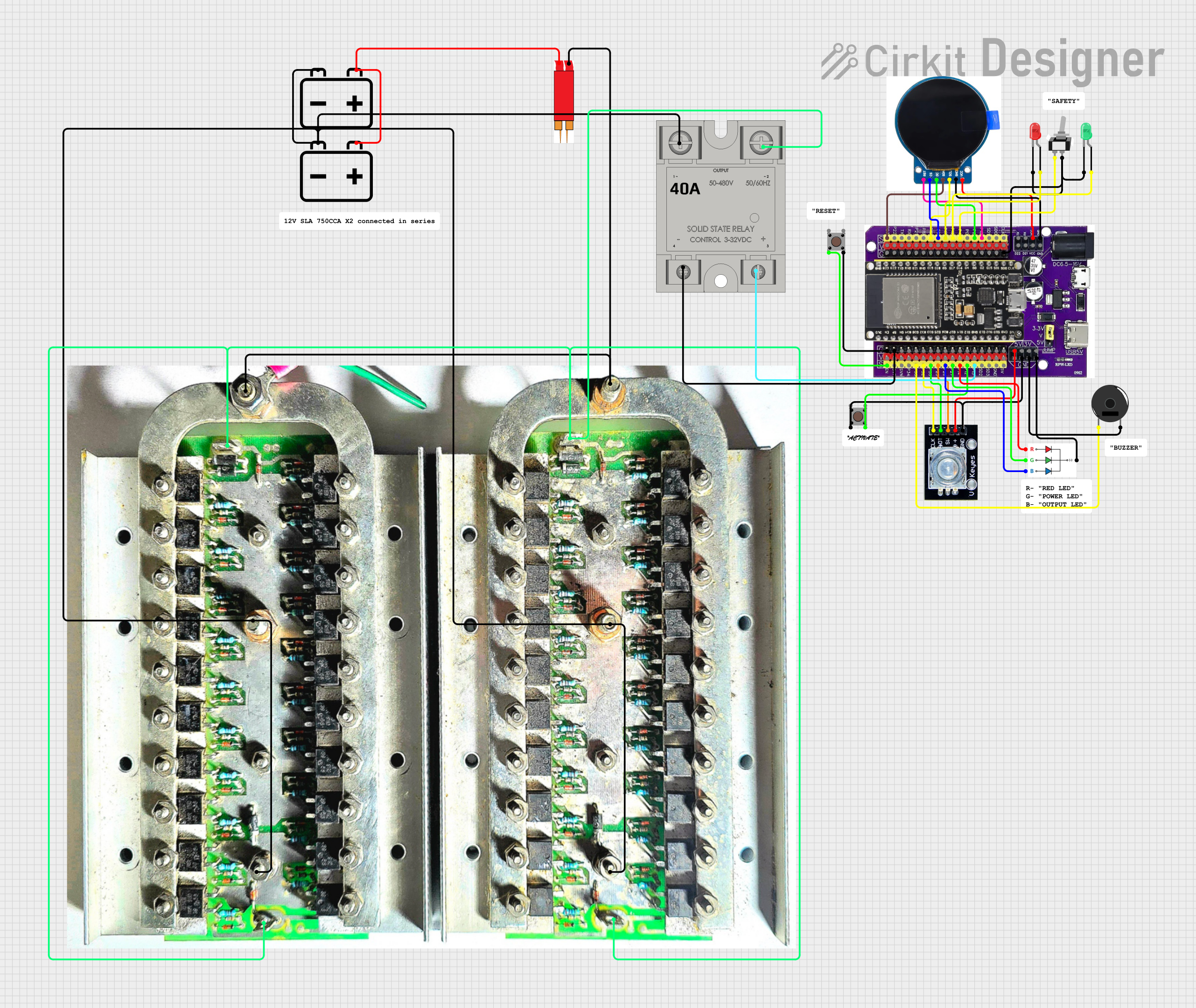
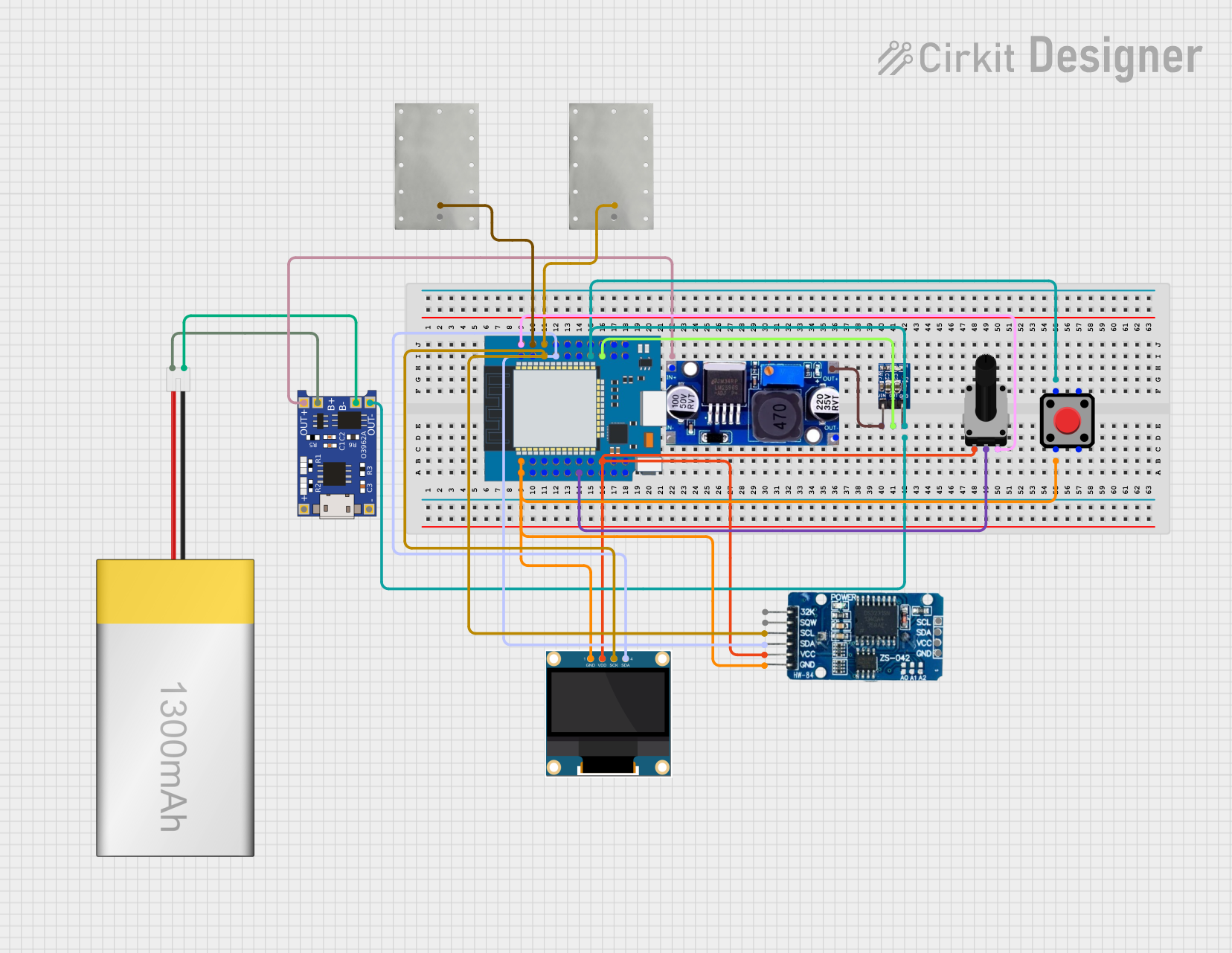

Explore Projects Built with Screen Printed Electrode
Common Applications and Use Cases
- Biosensors: Detection of glucose, cholesterol, and other biomolecules.
- Environmental Monitoring: Measurement of heavy metals, pH, and pollutants in water or soil.
- Food Safety: Detection of contaminants or quality control in food products.
- Medical Diagnostics: Point-of-care testing for various diseases.
- Research and Development: Electrochemical studies in academic and industrial labs.
Technical Specifications
Key Technical Details
- Material: Carbon, silver, gold, or platinum-based conductive inks.
- Substrate: Ceramic, plastic, or flexible polymer.
- Working Electrode Area: Typically 1–5 mm².
- Operating Voltage Range: -1.5 V to +1.5 V (varies by material and application).
- Temperature Range: -10°C to +60°C (depending on substrate and ink).
- Shelf Life: Up to 12 months when stored in a dry, cool environment.
Pin Configuration and Descriptions
Screen Printed Electrodes typically consist of three main electrodes: the working electrode (WE), the reference electrode (RE), and the counter electrode (CE). These are connected to an electrochemical analyzer or potentiostat.
| Pin/Connection | Description |
|---|---|
| Working Electrode (WE) | The electrode where the electrochemical reaction of interest occurs. Typically made of carbon, gold, or platinum. |
| Reference Electrode (RE) | Provides a stable reference potential for accurate measurements. Often made of silver/silver chloride (Ag/AgCl). |
| Counter Electrode (CE) | Completes the circuit by allowing current to flow. Usually made of carbon or platinum. |
Usage Instructions
How to Use the Component in a Circuit
Connect the Electrodes:
- Attach the working electrode (WE), reference electrode (RE), and counter electrode (CE) to the corresponding terminals of your electrochemical analyzer or potentiostat.
- Ensure proper alignment and secure connections to avoid signal noise.
Prepare the Sample:
- Place a small droplet (e.g., 5–50 µL) of the analyte solution onto the working electrode area.
- Allow the solution to spread evenly without overflowing onto other electrodes.
Run the Measurement:
- Configure the electrochemical analyzer with the appropriate parameters (e.g., potential range, scan rate).
- Start the measurement (e.g., cyclic voltammetry, chronoamperometry) and record the data.
Clean or Dispose:
- If the SPE is reusable, clean it gently with deionized water and dry it thoroughly.
- For disposable SPEs, safely discard them after use.
Important Considerations and Best Practices
- Storage: Store SPEs in a dry, cool environment to prevent degradation of the conductive materials.
- Avoid Contamination: Handle the electrodes with clean gloves or tweezers to avoid contamination.
- Calibration: Regularly calibrate your system using standard solutions to ensure accurate results.
- Sample Volume: Use the recommended sample volume to avoid short-circuiting or incomplete coverage of the working electrode.
Example Code for Arduino UNO
If you are using an SPE with an Arduino UNO for basic potentiometric measurements, you can use the following code to read voltage values from the working electrode:
// Example code for reading voltage from a Screen Printed Electrode (SPE)
// connected to an Arduino UNO. The working electrode (WE) is connected to
// analog pin A0, and the reference electrode (RE) is connected to ground.

const int wePin = A0; // Analog pin connected to the working electrode (WE)

void setup() {
  Serial.begin(9600); // Initialize serial communication at 9600 baud
  pinMode(wePin, INPUT); // Set the working electrode pin as input
}

void loop() {
  int sensorValue = analogRead(wePin); // Read the analog value from the WE
  float voltage = sensorValue * (5.0 / 1023.0); // Convert to voltage (0-5V)

  // Print the voltage to the Serial Monitor
  Serial.print("Voltage (V): ");
  Serial.println(voltage);

  delay(1000); // Wait for 1 second before the next reading
}
Troubleshooting and FAQs
Common Issues and Solutions
No Signal or Weak Response:
- Cause: Poor connection between the SPE and the analyzer.
- Solution: Check and secure all connections. Ensure the electrodes are properly aligned.
High Noise in Measurements:
- Cause: Contaminated electrodes or environmental interference.
- Solution: Clean the electrodes with deionized water and ensure the setup is in a low-noise environment.
Irregular Peaks in Cyclic Voltammetry:
- Cause: Insufficient sample volume or improper electrode cleaning.
- Solution: Use the recommended sample volume and clean the electrodes thoroughly.
Electrode Degradation:
- Cause: Prolonged use or exposure to harsh chemicals.
- Solution: Replace the SPE if it shows visible damage or inconsistent results.
FAQs
Q: Can I reuse a Screen Printed Electrode?
- A: Some SPEs are reusable if cleaned properly, but many are designed for single use to ensure accuracy and prevent contamination.
Q: What is the typical lifespan of an SPE?
- A: When stored correctly, SPEs can last up to 12 months. However, their lifespan during use depends on the application and cleaning process.
Q: Can I use an SPE for non-aqueous solutions?
- A: Yes, but ensure the electrode material is compatible with the solvent to avoid damage.
Q: How do I choose the right SPE material?
- A: Select the material based on your application. For example, carbon is versatile, gold is ideal for biosensing, and platinum is suitable for high-temperature applications.