How to Use MAX98375: Examples, Pinouts, and Specs
Introduction
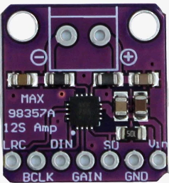
The MAX98375 is a high-efficiency, Class D audio amplifier with integrated digital signal processing (DSP) capabilities. It is designed to deliver high-quality audio output while maintaining low power consumption, making it ideal for portable and battery-powered applications. The component supports I²S digital audio input and features advanced protection mechanisms, such as overcurrent and thermal protection, ensuring reliable operation in various environments.
Explore Projects Built with MAX98375


Explore Projects Built with MAX98375
Common Applications
- Portable speakers
- Smart home devices
- Wearable electronics
- IoT devices with audio output
- Battery-powered audio systems
Technical Specifications
Key Technical Details
| Parameter | Value |
|---|---|
| Supply Voltage (VDD) | 2.5V to 5.5V |
| Output Power | Up to 15W (at 10% THD, 8Ω load, 5V VDD) |
| Efficiency | >90% |
| Input Type | I²S digital audio |
| Signal-to-Noise Ratio (SNR) | 98 dB |
| Total Harmonic Distortion | 0.02% (at 1W, 8Ω load, 1kHz) |
| Operating Temperature | -40°C to +85°C |
| Package Type | 20-pin WLP or TQFN |
Pin Configuration and Descriptions
WLP Package Pinout
| Pin Number | Pin Name | Description |
|---|---|---|
| A1 | VDD | Power supply input (2.5V to 5.5V). |
| A2 | GND | Ground connection. |
| A3 | OUT+ | Positive speaker output. |
| A4 | OUT- | Negative speaker output. |
| B1 | SCL | I²C clock input for control interface. |
| B2 | SDA | I²C data input/output for control interface. |
| B3 | DIN | I²S digital audio data input. |
| B4 | BCLK | I²S bit clock input. |
| C1 | LRCLK | I²S left/right clock input. |
| C2 | MCLK | Master clock input for I²S. |
| C3 | PVDD | Power supply for the output stage. |
| C4 | NC | No connection. Leave unconnected. |
TQFN Package Pinout
| Pin Number | Pin Name | Description |
|---|---|---|
| 1 | VDD | Power supply input (2.5V to 5.5V). |
| 2 | GND | Ground connection. |
| 3 | OUT+ | Positive speaker output. |
| 4 | OUT- | Negative speaker output. |
| 5 | SCL | I²C clock input for control interface. |
| 6 | SDA | I²C data input/output for control interface. |
| 7 | DIN | I²S digital audio data input. |
| 8 | BCLK | I²S bit clock input. |
| 9 | LRCLK | I²S left/right clock input. |
| 10 | MCLK | Master clock input for I²S. |
| 11 | PVDD | Power supply for the output stage. |
| 12 | NC | No connection. Leave unconnected. |
Usage Instructions
How to Use the MAX98375 in a Circuit
- Power Supply: Connect the VDD pin to a stable power source within the range of 2.5V to 5.5V. Use decoupling capacitors (e.g., 10µF and 0.1µF) close to the VDD pin to reduce noise.
- Speaker Connection: Connect the speaker terminals to the OUT+ and OUT- pins. Ensure the speaker impedance matches the amplifier's specifications (e.g., 8Ω or 4Ω).
- I²S Audio Input:
- Connect the I²S signals (DIN, BCLK, LRCLK, and MCLK) to the corresponding pins.
- Ensure the I²S format and clock frequencies are compatible with the MAX98375.
- I²C Control: If using the I²C interface for configuration, connect the SCL and SDA pins to the I²C bus. Pull-up resistors (e.g., 4.7kΩ) are required on these lines.
- Thermal Management: Ensure proper heat dissipation by following the recommended PCB layout guidelines provided in the datasheet.
Important Considerations
- Use proper decoupling capacitors on the power supply lines to minimize noise and ensure stable operation.
- Avoid exceeding the maximum voltage and current ratings to prevent damage to the component.
- Follow the recommended PCB layout guidelines to minimize electromagnetic interference (EMI) and optimize thermal performance.
Example: Using MAX98375 with Arduino UNO
The MAX98375 can be interfaced with an Arduino UNO for basic audio playback. Below is an example code snippet to configure the I²C interface and send audio data via I²S.
#include <Wire.h> // Include the Wire library for I²C communication

#define MAX98375_I2C_ADDRESS 0x10 // Replace with the actual I²C address

void setup() {
  Wire.begin(); // Initialize I²C communication
  Serial.begin(9600); // Initialize serial communication for debugging

  // Configure MAX98375 via I²C
  Wire.beginTransmission(MAX98375_I2C_ADDRESS);
  Wire.write(0x00); // Example register address
  Wire.write(0x01); // Example configuration value
  Wire.endTransmission();

  Serial.println("MAX98375 configured successfully.");
}

void loop() {
  // Audio data should be sent via I²S (not directly supported by Arduino UNO).
  // Use an external I²S module or microcontroller with native I²S support.
}
Troubleshooting and FAQs
Common Issues and Solutions
No Audio Output:
- Verify the power supply voltage is within the specified range (2.5V to 5.5V).
- Check the I²S connections and ensure the audio source is active.
- Confirm the speaker is properly connected to the OUT+ and OUT- pins.
Distorted Audio:
- Ensure the input audio signal format matches the MAX98375's supported I²S configuration.
- Check the speaker impedance and ensure it is within the recommended range.
- Verify that the power supply can provide sufficient current for the desired output power.
Overheating:
- Ensure proper heat dissipation by following the recommended PCB layout guidelines.
- Reduce the output power if the device is operating near its thermal limits.
FAQs
Q: Can the MAX98375 drive headphones?
A: No, the MAX98375 is designed for driving speakers. For headphones, use a dedicated headphone amplifier.
Q: What is the maximum supported sampling rate for I²S input?
A: The MAX98375 supports I²S sampling rates up to 192kHz.
Q: Is the MAX98375 suitable for stereo audio applications?
A: The MAX98375 is a mono amplifier. For stereo applications, use two MAX98375 devices or a stereo amplifier.
Q: Can I use the MAX98375 without I²C configuration?
A: Yes, the MAX98375 can operate in a default configuration without I²C programming. However, I²C allows for advanced customization and control.