How to Use RFID WS1850s : Examples, Pinouts, and Specs
Introduction
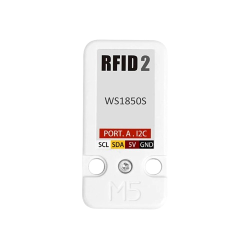
The RFID WS1850s, manufactured by M5Stack, is a compact and efficient RFID reader module designed for short-range communication with RFID tags. Operating at a frequency of 13.56 MHz, this module is ideal for applications such as access control, inventory management, and identification systems. Its small form factor and support for multiple communication protocols make it easy to integrate into microcontroller-based projects, including Arduino and other development platforms.
Explore Projects Built with RFID WS1850s
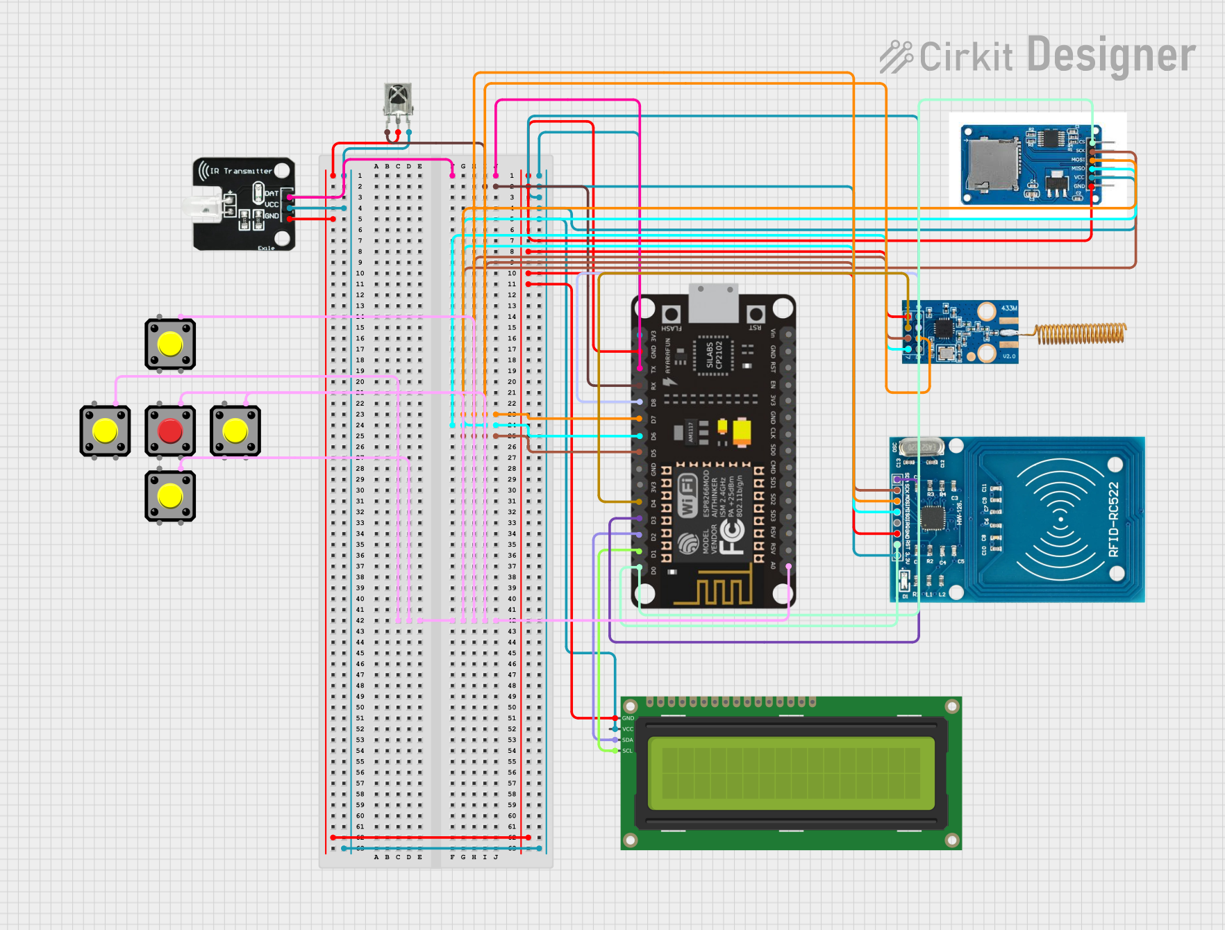
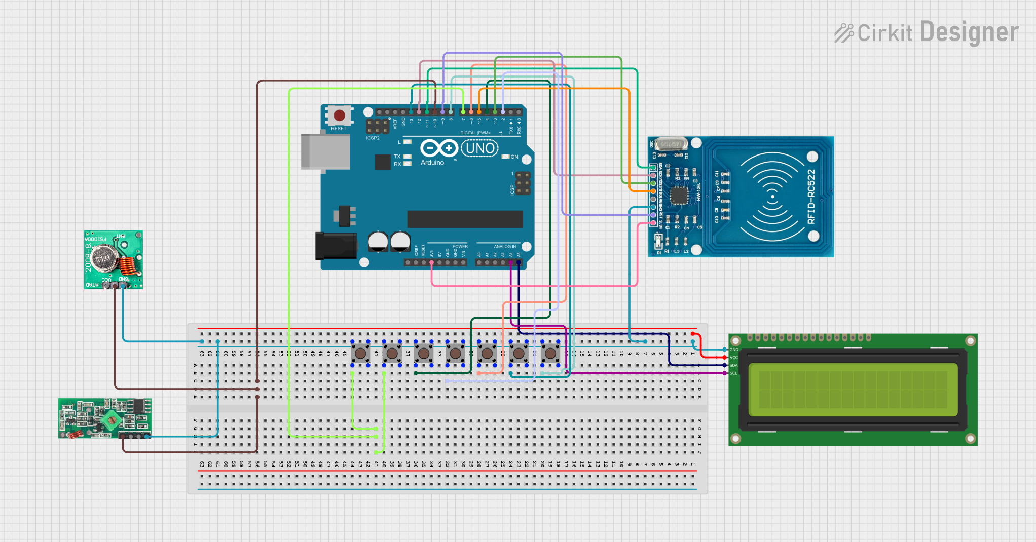
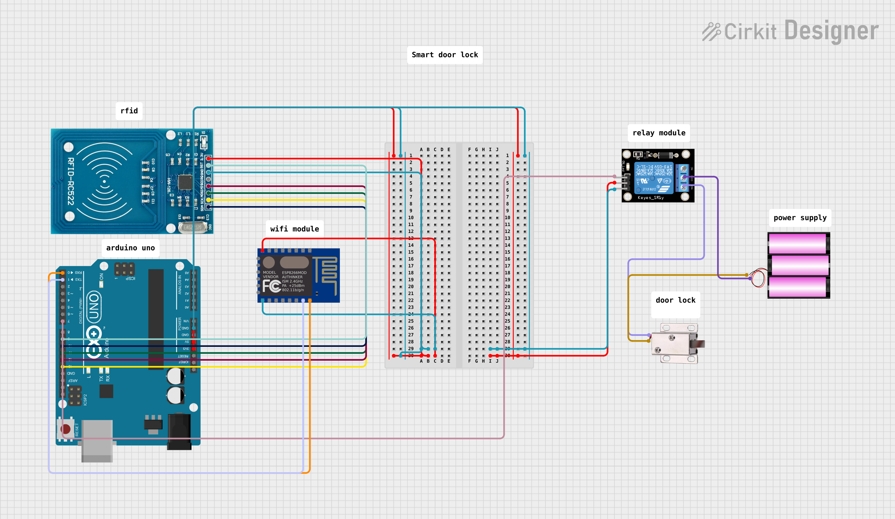
Explore Projects Built with RFID WS1850s
Common Applications
- Access control systems (e.g., door locks, employee ID verification)
- Inventory and asset tracking
- Contactless payment systems
- Library management systems
- Identification and authentication systems
Technical Specifications
Below are the key technical details of the RFID WS1850s module:
| Parameter | Specification |
|---|---|
| Operating Frequency | 13.56 MHz |
| Communication Protocols | UART, I2C |
| Operating Voltage | 3.3V - 5V |
| Current Consumption | < 50mA |
| Reading Distance | Up to 5 cm (depending on tag type) |
| Supported RFID Tags | ISO/IEC 14443 Type A |
| Dimensions | 40mm x 40mm x 10mm |
| Operating Temperature | -20°C to 70°C |
Pin Configuration
The RFID WS1850s module has a simple pinout for easy integration. Below is the pin configuration:
| Pin | Name | Description |
|---|---|---|
| 1 | GND | Ground (0V reference) |
| 2 | VCC | Power supply (3.3V - 5V) |
| 3 | TX | UART Transmit (data output) |
| 4 | RX | UART Receive (data input) |
| 5 | SDA | I2C Data Line |
| 6 | SCL | I2C Clock Line |
| 7 | RST | Reset pin (active low) |
Usage Instructions
Connecting the RFID WS1850s to an Arduino UNO
The RFID WS1850s can be easily connected to an Arduino UNO using either UART or I2C communication. Below is an example of how to connect the module using UART:
| RFID WS1850s Pin | Arduino UNO Pin |
|---|---|
| GND | GND |
| VCC | 5V |
| TX | Pin 2 (RX) |
| RX | Pin 3 (TX) |
Sample Code for Arduino
The following Arduino sketch demonstrates how to read data from the RFID WS1850s using UART communication:
#include <SoftwareSerial.h>

// Define RX and TX pins for SoftwareSerial
SoftwareSerial RFID(2, 3); // RX = Pin 2, TX = Pin 3

void setup() {
  Serial.begin(9600); // Initialize Serial Monitor
  RFID.begin(9600);   // Initialize RFID module communication

  Serial.println("RFID WS1850s Reader Initialized");
}

void loop() {
  if (RFID.available()) {
    // Read data from the RFID module
    String tagData = "";
    while (RFID.available()) {
      char c = RFID.read();
      tagData += c; // Append each character to the tagData string
    }

    // Print the tag data to the Serial Monitor
    Serial.print("RFID Tag Detected: ");
    Serial.println(tagData);
  }
}
Important Considerations
- Power Supply: Ensure the module is powered with a stable voltage between 3.3V and 5V.
- Reading Distance: The effective reading distance is up to 5 cm, depending on the type of RFID tag used.
- Communication Protocol: Choose between UART or I2C based on your project requirements. For UART, ensure the baud rate matches the module's default (9600 bps).
- Reset Pin: Use the RST pin to reset the module if it becomes unresponsive.
Troubleshooting and FAQs
Common Issues and Solutions
No Data Received from the Module
- Cause: Incorrect wiring or mismatched baud rate.
- Solution: Double-check the connections and ensure the RX and TX pins are correctly connected. Verify that the baud rate in your code matches the module's default (9600 bps).
Short Reading Distance
- Cause: Poor quality or incompatible RFID tag.
- Solution: Use high-quality RFID tags that comply with ISO/IEC 14443 Type A standards.
Module Not Powering On
- Cause: Insufficient power supply or incorrect voltage.
- Solution: Ensure the power supply provides a stable voltage between 3.3V and 5V.
Interference with Other Devices
- Cause: Electromagnetic interference from nearby devices.
- Solution: Keep the RFID module away from other electronic devices that may cause interference.
FAQs
Q1: Can the RFID WS1850s read multiple tags simultaneously?
A1: No, the RFID WS1850s is designed to read one tag at a time.
Q2: What is the maximum cable length for connecting the module?
A2: For UART communication, keep the cable length under 1 meter to avoid signal degradation. For I2C, use pull-up resistors and keep the length as short as possible.
Q3: Can I use the RFID WS1850s with a 3.3V microcontroller?
A3: Yes, the module supports both 3.3V and 5V logic levels, making it compatible with a wide range of microcontrollers.
Q4: How do I change the communication protocol from UART to I2C?
A4: Refer to the manufacturer's documentation for instructions on switching between UART and I2C modes. This may involve configuring specific pins or sending initialization commands.
By following this documentation, you can effectively integrate the RFID WS1850s into your projects and troubleshoot common issues with ease.