
How to Use PDP: Examples, Pinouts, and Specs

 Design with PDP in Cirkit Designer
Introduction
The Power Distribution Panel (PDP) by Cross The Road Electronics is a robust and efficient device designed to distribute power from a single source to multiple circuits. It is commonly used in robotics, industrial automation, and other electrical systems requiring centralized power management. The PDP ensures safe and reliable power distribution while providing real-time monitoring of voltage and current for connected devices.
Explore Projects Built with PDP
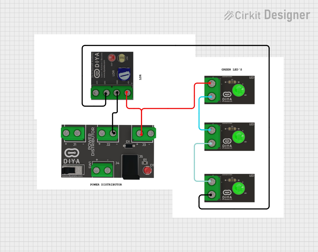 Open Project in Cirkit Designer
 Open Project in Cirkit Designer
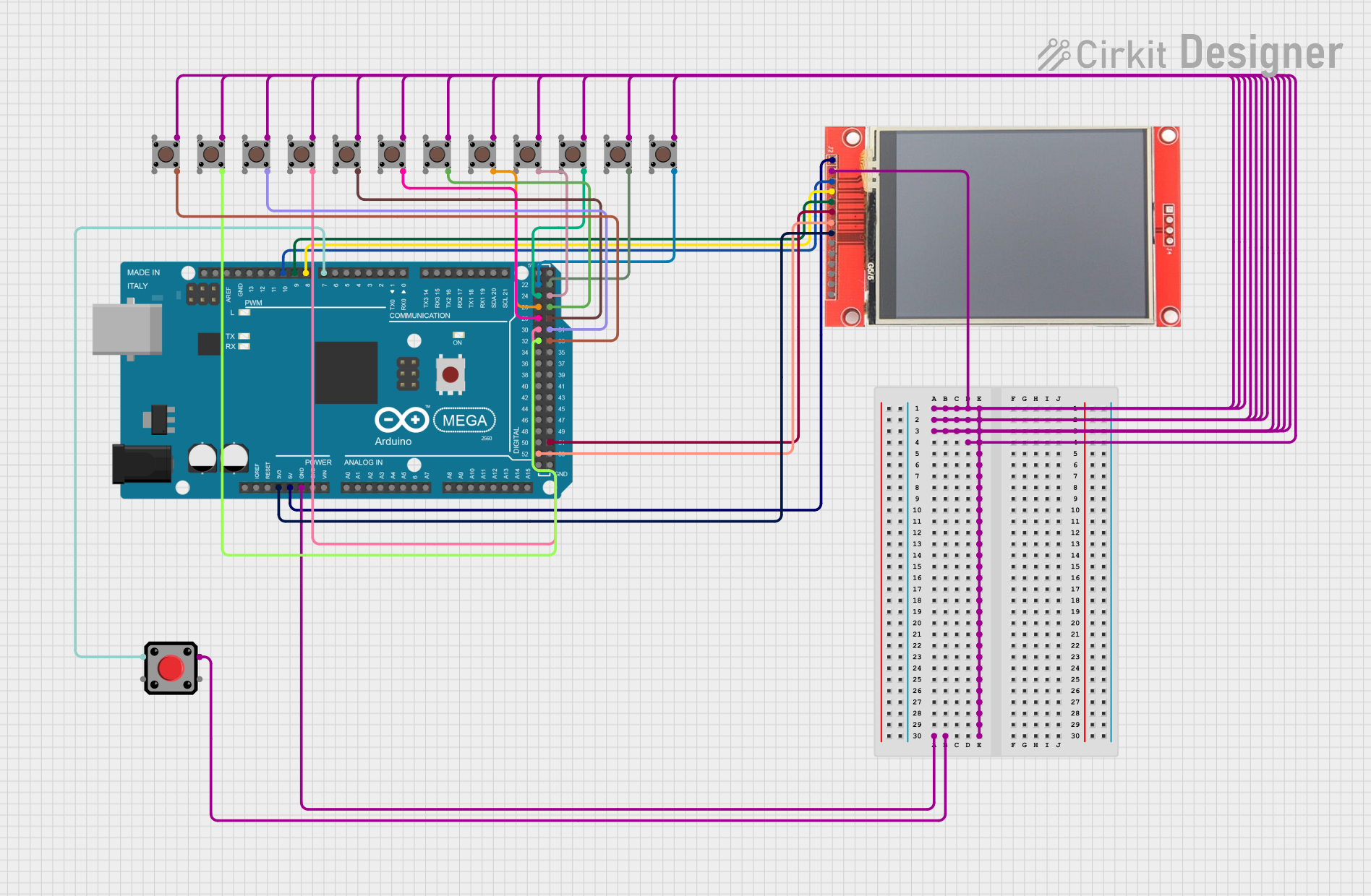 Open Project in Cirkit Designer
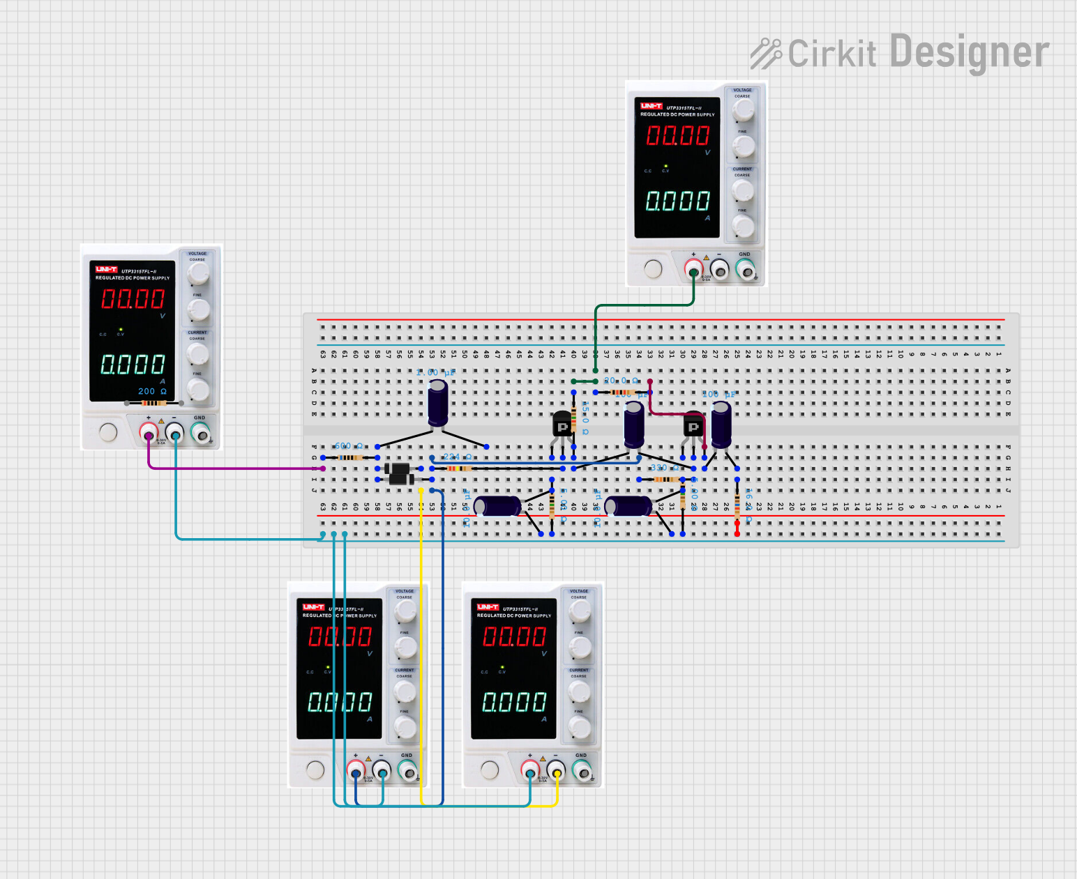 Open Project in Cirkit Designer
Explore Projects Built with PDP
Open Project in Cirkit DesignerOpen Project in Cirkit DesignerOpen Project in Cirkit DesignerOpen Project in Cirkit DesignerCommon Applications and Use Cases
- Robotics (e.g., FIRST Robotics Competition)
- Industrial automation systems
- Power management in custom electronics projects
- Multi-circuit power distribution in vehicles or machinery
- Monitoring and troubleshooting electrical systems
Technical Specifications
The PDP is engineered to handle high-current loads and provide detailed power diagnostics. Below are the key technical specifications:
General Specifications
| Parameter | Value |
|---|---|
| Manufacturer | Cross The Road Electronics |
| Part ID | Power Distribution Panel (PDP) |
| Input Voltage Range | 6.8V to 16V |
| Maximum Current | 120A (total) |
| Number of Output Channels | 16 |
| Communication Interface | CAN (Controller Area Network) |
| Dimensions | 6.25" x 3.25" x 1.25" |
| Weight | 0.85 lbs (385 g) |
Pin Configuration and Descriptions
The PDP features multiple input and output terminals for power distribution and monitoring. Below is the pin configuration:
Power Input Terminals
| Pin Name | Description |
|---|---|
| +12V Input | Main positive power input (6.8V–16V) |
| GND Input | Main ground connection |
Power Output Channels
| Channel Number | Description |
|---|---|
| 1–16 | High-current output channels for devices |
Communication and Monitoring
| Pin Name | Description |
|---|---|
| CAN_H | CAN bus high signal |
| CAN_L | CAN bus low signal |
| Status LED | Indicates power and fault status |
Usage Instructions
The PDP is straightforward to integrate into electrical systems. Follow these steps for proper usage:
Step 1: Power Input Connection
- Connect the main power source to the
+12V InputandGND Inputterminals. - Ensure the input voltage is within the range of 6.8V to 16V to avoid damage.
Step 2: Connecting Devices
- Connect the devices or circuits to the output channels (1–16).
- Each channel is protected by an internal circuit breaker, so no additional fuses are required.
Step 3: Communication Setup (Optional)
- If using the CAN interface, connect the
CAN_HandCAN_Lpins to your CAN bus network. - Configure the PDP's CAN ID using the manufacturer's software or tools.
Step 4: Monitoring and Diagnostics
- Use the status LED to check the operational state:
- Solid green: Normal operation
- Blinking red: Fault detected
- For detailed diagnostics, connect the PDP to a compatible controller or software via the CAN interface.
Important Considerations
- Ensure all connections are secure to prevent power loss or short circuits.
- Do not exceed the maximum current rating of 120A across all channels.
- Use appropriately sized wires for input and output connections to handle the expected current.
Example: Using the PDP with an Arduino UNO
While the PDP is primarily designed for high-power systems, it can be monitored using an Arduino UNO via the CAN interface. Below is an example code snippet:
#include <SPI.h>
#include <mcp_can.h>

// Define CAN bus pins for Arduino UNO
#define CAN_CS_PIN 10
#define CAN_INT_PIN 2

// Initialize the MCP2515 CAN controller
MCP_CAN CAN(CAN_CS_PIN);

void setup() {
  Serial.begin(9600);

  // Initialize CAN bus at 500 kbps
  if (CAN.begin(MCP_ANY, 500000, MCP_8MHZ) == CAN_OK) {
    Serial.println("CAN bus initialized successfully!");
  } else {
    Serial.println("Error initializing CAN bus.");
    while (1);
  }

  // Set CAN bus to normal mode
  CAN.setMode(MCP_NORMAL);
  Serial.println("CAN bus set to normal mode.");
}

void loop() {
  // Check for incoming CAN messages
  if (CAN.checkReceive() == CAN_MSGAVAIL) {
    long unsigned int id;
    unsigned char len;
    unsigned char buf[8];

    // Read the CAN message
    CAN.readMsgBuf(&id, &len, buf);

    // Print the message ID and data
    Serial.print("Message ID: 0x");
    Serial.println(id, HEX);
    Serial.print("Data: ");
    for (int i = 0; i < len; i++) {
      Serial.print(buf[i], HEX);
      Serial.print(" ");
    }
    Serial.println();
  }
}
Note: The above code requires the MCP_CAN library and an MCP2515 CAN module to interface with the PDP.
Troubleshooting and FAQs
Common Issues
PDP does not power on:
- Check the input voltage and ensure it is within the specified range (6.8V–16V).
- Verify that the power source is functioning correctly.
No power on output channels:
- Ensure the connected devices are within the current limits of the channels.
- Check for tripped circuit breakers and reset them if necessary.
CAN communication not working:
- Verify the CAN bus wiring and termination resistors.
- Ensure the PDP's CAN ID matches the configuration in your software.
Status LED blinking red:
- This indicates a fault condition. Check for short circuits or overcurrent on the output channels.
FAQs
Q: Can the PDP handle 24V systems?
A: No, the PDP is designed for systems with an input voltage range of 6.8V to 16V.
Q: How do I reset a tripped circuit breaker?
A: The PDP's circuit breakers are self-resetting. Remove the fault condition, and the breaker will reset automatically.
Q: Can I use the PDP without the CAN interface?
A: Yes, the PDP can function as a standalone power distribution device without using the CAN interface.
Q: What wire gauge should I use for connections?
A: Use wires rated for the expected current. For high-current inputs, 10 AWG or thicker is recommended.
By following this documentation, you can effectively integrate and utilize the Power Distribution Panel in your projects.