How to Use PModSSD 7 Segment Display: Examples, Pinouts, and Specs
Introduction
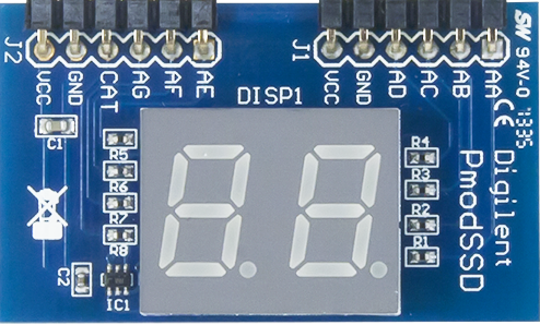
The Pmod SSD (Revision A), manufactured by Digilent, is a 7-segment display module designed for displaying decimal numbers and select alphanumeric characters. It consists of two 7-segment displays, each with seven individual LED segments and a decimal point. The module is ideal for applications requiring simple numeric or limited alphanumeric output, such as counters, timers, or basic user interfaces.
Explore Projects Built with PModSSD 7 Segment Display
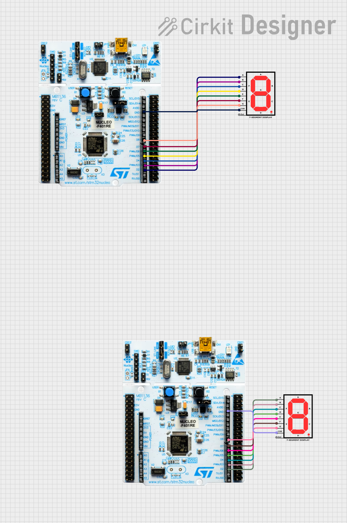

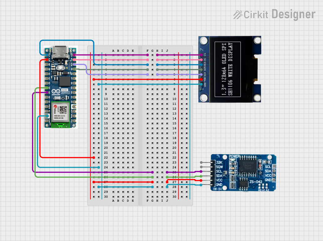
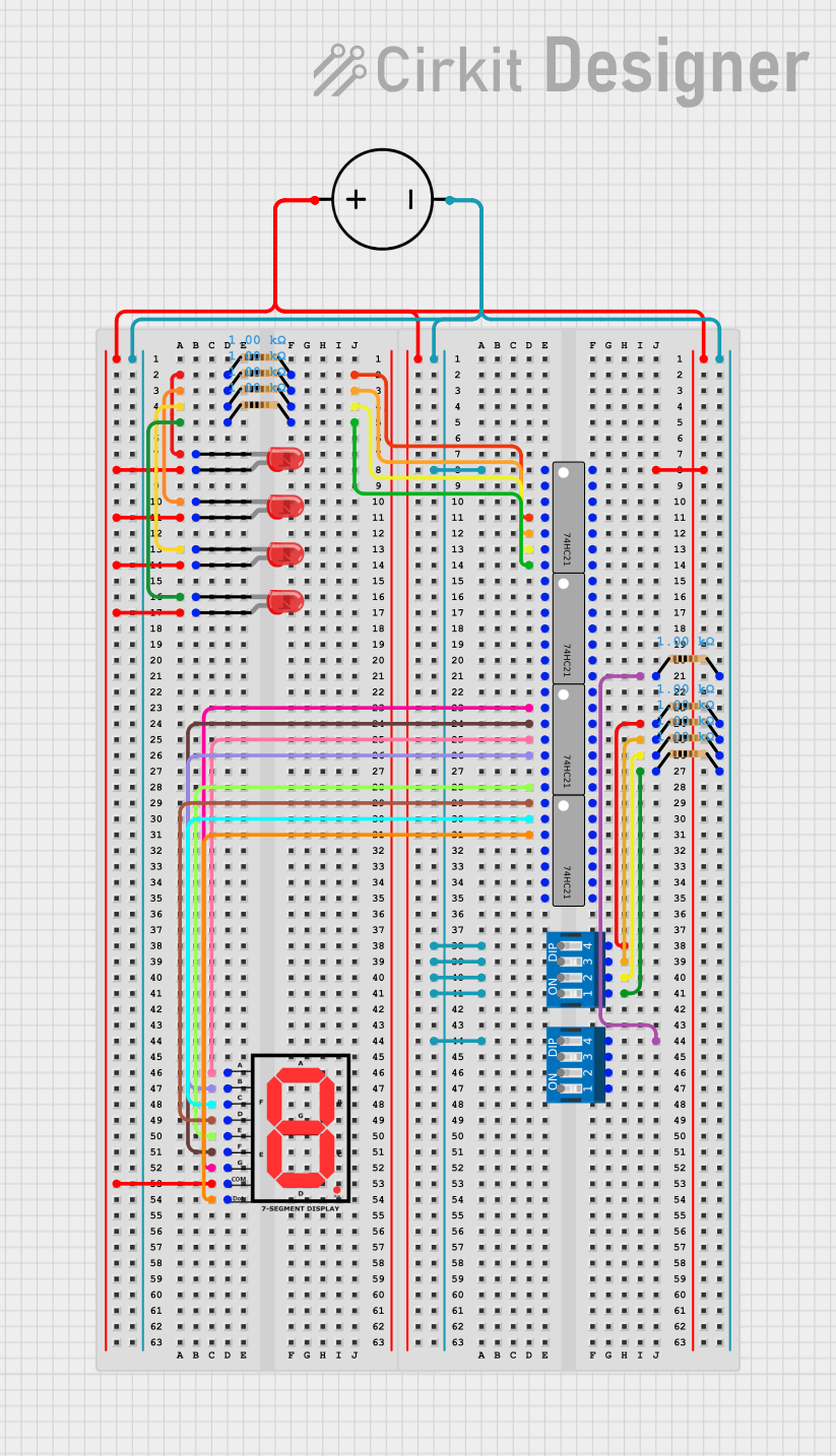
Explore Projects Built with PModSSD 7 Segment Display
Common Applications and Use Cases
- Digital clocks and timers
- Counter displays
- Basic numeric output for embedded systems
- Educational projects and prototyping
- Debugging tools for microcontroller-based systems
Technical Specifications
Key Technical Details
- Manufacturer Part ID: Pmod SSD (Revision A)
- Operating Voltage: 3.3V or 5V (logic level compatible)
- Current Consumption: ~20mA per segment (typical)
- Interface: 12-pin Pmod connector (SPI-based communication)
- Display Type: Two 7-segment LED displays with decimal points
- Dimensions: 1.0" × 1.8" (25.4mm × 45.7mm)
Pin Configuration and Descriptions
The Pmod SSD uses a 12-pin connector for communication and power. The pinout is as follows:
| Pin | Name | Description |
|---|---|---|
| 1 | CS | Chip Select (Active Low) |
| 2 | SDO | Serial Data Out (SPI Data) |
| 3 | SDI | Serial Data In (SPI Data) |
| 4 | SCK | Serial Clock (SPI Clock) |
| 5 | GND | Ground |
| 6 | VCC | Power Supply (3.3V or 5V) |
| 7 | NC | Not Connected |
| 8 | NC | Not Connected |
| 9 | NC | Not Connected |
| 10 | NC | Not Connected |
| 11 | NC | Not Connected |
| 12 | NC | Not Connected |
Note: Pins 7–12 are not used in this module and should be left unconnected.
Usage Instructions
How to Use the Pmod SSD in a Circuit
- Power Supply: Connect the VCC pin to a 3.3V or 5V power source and the GND pin to ground.
- SPI Communication: Use an SPI-compatible microcontroller (e.g., Arduino, Raspberry Pi) to send data to the display. Connect the SPI pins (CS, SDO, SDI, SCK) to the corresponding pins on your microcontroller.
- Data Format: The Pmod SSD requires data to be sent in a specific format to control the segments. Each digit is controlled by sending a byte that represents the desired segments to illuminate.
Important Considerations and Best Practices
- Current Limiting: Ensure the power supply can handle the current requirements of the display. Each segment consumes ~20mA, so the total current can add up quickly.
- SPI Configuration: Configure the SPI interface with the correct clock polarity and phase (CPOL = 0, CPHA = 0).
- Refresh Rate: Continuously refresh the display at a sufficient rate (e.g., 60Hz) to avoid flickering.
- Avoid Overvoltage: Do not exceed the recommended operating voltage of 5V to prevent damage to the module.
Example Code for Arduino UNO
Below is an example of how to interface the Pmod SSD with an Arduino UNO using SPI:
#include <SPI.h>

// Define SPI pins for the Pmod SSD
const int CS_PIN = 10; // Chip Select pin

// Segment data for digits 0-9 (common cathode configuration)
const byte digitData[10] = {
  0b00111111, // 0
  0b00000110, // 1
  0b01011011, // 2
  0b01001111, // 3
  0b01100110, // 4
  0b01101101, // 5
  0b01111101, // 6
  0b00000111, // 7
  0b01111111, // 8
  0b01101111  // 9
};

void setup() {
  // Initialize SPI and set the CS pin as output
  SPI.begin();
  pinMode(CS_PIN, OUTPUT);
  digitalWrite(CS_PIN, HIGH); // Set CS pin high (inactive)
}

void loop() {
  // Display the number "42" on the Pmod SSD
  displayDigit(4, 1); // Display "4" on the left digit
  displayDigit(2, 2); // Display "2" on the right digit
  delay(1000);        // Wait for 1 second
}

// Function to display a digit on the Pmod SSD
void displayDigit(int digit, int position) {
  if (digit < 0 || digit > 9 || position < 1 || position > 2) {
    return; // Invalid input, do nothing
  }

  digitalWrite(CS_PIN, LOW); // Activate the Pmod SSD

  // Send position and digit data
  SPI.transfer(position);       // Send position (1 = left, 2 = right)
  SPI.transfer(digitData[digit]); // Send segment data for the digit

  digitalWrite(CS_PIN, HIGH); // Deactivate the Pmod SSD
}
Explanation of the Code:
- The
digitDataarray contains the segment data for digits 0–9. - The
displayDigitfunction sends the position (1 for left, 2 for right) and the corresponding segment data to the Pmod SSD. - The
loopfunction demonstrates how to display the number "42" on the module.
Troubleshooting and FAQs
Common Issues and Solutions
Display Not Lighting Up:
- Ensure the power supply is connected correctly and provides sufficient current.
- Verify that the SPI pins are correctly connected to the microcontroller.
Incorrect Digits Displayed:
- Check the data being sent to the display. Ensure the
digitDataarray matches the desired segment configuration. - Verify the SPI clock polarity and phase settings (CPOL = 0, CPHA = 0).
- Check the data being sent to the display. Ensure the
Flickering Display:
- Increase the refresh rate of the display to at least 60Hz.
- Ensure stable power supply voltage and current.
One Digit Not Working:
- Check the connections for the specific digit.
- Verify that the position byte (1 or 2) is being sent correctly.
FAQs
Q: Can the Pmod SSD display letters?
A: Yes, it can display some letters (e.g., A, b, C, d, E, F) by illuminating specific segments. However, the display is primarily designed for numeric output.
Q: Is the Pmod SSD compatible with 5V logic?
A: Yes, the Pmod SSD is compatible with both 3.3V and 5V logic levels.
Q: Can I use the Pmod SSD with a Raspberry Pi?
A: Yes, the Pmod SSD can be used with any SPI-compatible device, including the Raspberry Pi. Ensure proper SPI configuration and voltage compatibility.
Q: How do I control the decimal points?
A: The decimal points are controlled by specific bits in the segment data. Refer to the module's datasheet for details on enabling them.