Cirkit Designer
Your all-in-one circuit design IDE
Home /
Component Documentation
How to Use RelayModule14ChannelI2C: Examples, Pinouts, and Specs
Introduction
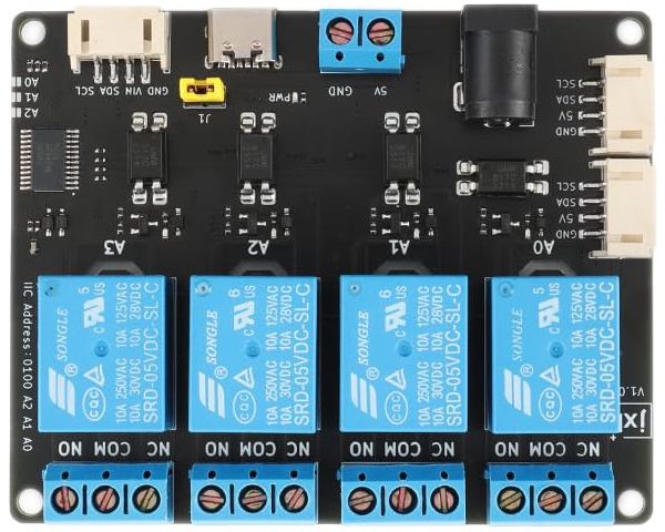
The RelayModule14ChannelI2C is a versatile 14-channel relay module designed to interface with microcontrollers via the I2C communication protocol. This module allows users to control up to 14 high-power devices, such as lights, motors, or appliances, with minimal wiring and efficient communication. Each relay can handle high current loads, making it ideal for home automation, industrial control systems, and robotics applications.
Explore Projects Built with RelayModule14ChannelI2C
Wi-Fi Controlled Smart Relay Switch with ESP8266 and MCP23017

This circuit is designed to control an 8-channel relay module via an ESP8266 microcontroller, which interfaces with an MCP23017 I/O expander over I2C. The ESP8266 connects to a WiFi network and subscribes to MQTT topics to receive commands for toggling the relays. Additionally, there are toggle switches connected to the MCP23017 that allow manual control of the relays, with the system's state being reported back via MQTT.
ESP32 and MCP23017-Based Smart Relay Control System with DHT22 Sensors

This circuit is a control system that uses an ESP32 microcontroller to manage multiple relays and read data from DHT22 temperature and humidity sensors. The DFRobot Gravity MCP23017 I2C module expands the GPIO capabilities of the ESP32, allowing it to control additional relays for switching high-power devices.
Arduino Nano Controlled Smart Relay with APDS-9960 Gesture Sensor
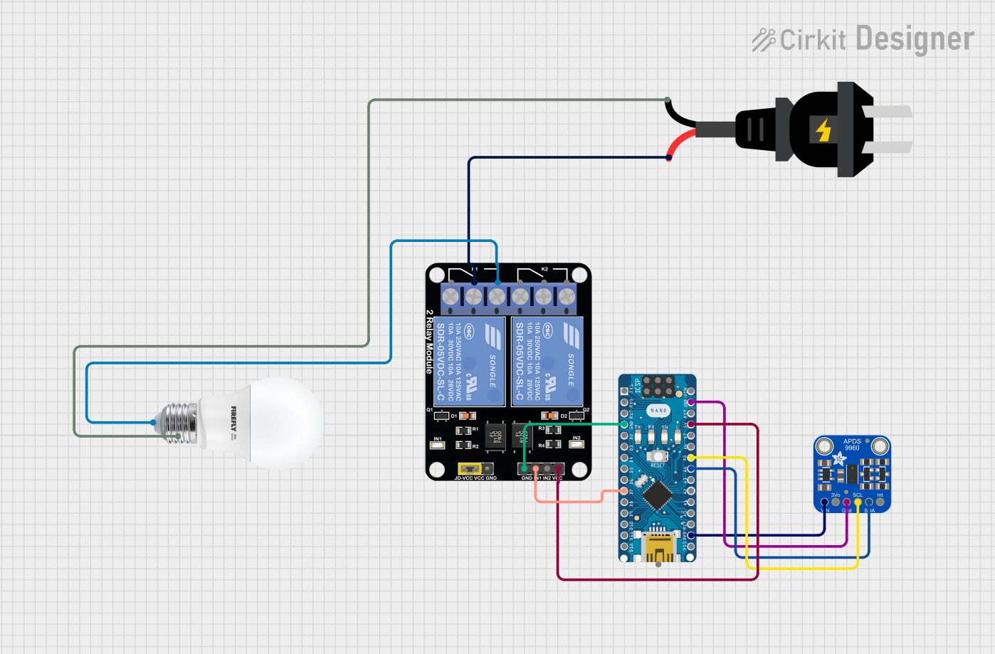
This circuit features an Arduino Nano microcontroller interfaced with an Adafruit APDS-9960 sensor and a 2-channel relay module. The APDS-9960 sensor, which is capable of gesture detection, is connected to the Arduino via I2C communication lines (SCL, SDA) and powered by the Arduino's 3.3V output. The relay module is controlled by the Arduino through a digital pin (D7) and is used to switch an AC-powered bulb on and off, with the relay's common (COM) terminal connected to the AC source and the normally open (NO1) terminal connected to the bulb.
ESP32-Based Automated Plant Watering System with Soil Moisture Sensing and RTC Scheduling
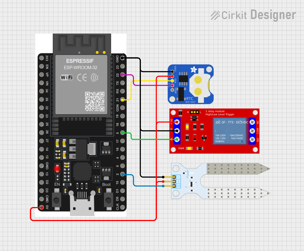
This circuit features an ESP32 microcontroller connected to a soil moisture sensor, a DS1307 real-time clock (RTC), and a 5V relay module. The ESP32 reads the soil moisture level and can control the relay based on time or moisture data, while the RTC provides accurate timekeeping. The relay can be used to switch external devices, potentially for plant watering systems, and the ESP32 communicates with the RTC via I2C protocol (SDA/SCL lines).
Explore Projects Built with RelayModule14ChannelI2C
Wi-Fi Controlled Smart Relay Switch with ESP8266 and MCP23017
This circuit is designed to control an 8-channel relay module via an ESP8266 microcontroller, which interfaces with an MCP23017 I/O expander over I2C. The ESP8266 connects to a WiFi network and subscribes to MQTT topics to receive commands for toggling the relays. Additionally, there are toggle switches connected to the MCP23017 that allow manual control of the relays, with the system's state being reported back via MQTT.
ESP32 and MCP23017-Based Smart Relay Control System with DHT22 Sensors
This circuit is a control system that uses an ESP32 microcontroller to manage multiple relays and read data from DHT22 temperature and humidity sensors. The DFRobot Gravity MCP23017 I2C module expands the GPIO capabilities of the ESP32, allowing it to control additional relays for switching high-power devices.
Arduino Nano Controlled Smart Relay with APDS-9960 Gesture Sensor
This circuit features an Arduino Nano microcontroller interfaced with an Adafruit APDS-9960 sensor and a 2-channel relay module. The APDS-9960 sensor, which is capable of gesture detection, is connected to the Arduino via I2C communication lines (SCL, SDA) and powered by the Arduino's 3.3V output. The relay module is controlled by the Arduino through a digital pin (D7) and is used to switch an AC-powered bulb on and off, with the relay's common (COM) terminal connected to the AC source and the normally open (NO1) terminal connected to the bulb.
ESP32-Based Automated Plant Watering System with Soil Moisture Sensing and RTC Scheduling
This circuit features an ESP32 microcontroller connected to a soil moisture sensor, a DS1307 real-time clock (RTC), and a 5V relay module. The ESP32 reads the soil moisture level and can control the relay based on time or moisture data, while the RTC provides accurate timekeeping. The relay can be used to switch external devices, potentially for plant watering systems, and the ESP32 communicates with the RTC via I2C protocol (SDA/SCL lines).
Common Applications and Use Cases
- Home Automation: Control lighting, fans, or other household appliances.
- Industrial Systems: Manage machinery or equipment in factories.
- Robotics: Operate actuators or motors in robotic systems.
- IoT Projects: Enable remote control of devices via microcontrollers or IoT platforms.
Technical Specifications
Key Technical Details
- Operating Voltage: 5V DC
- Relay Channels: 14
- Relay Type: SPDT (Single Pole Double Throw)
- Relay Voltage Rating: 250V AC / 30V DC (max)
- Relay Current Rating: 10A (max)
- Communication Protocol: I2C
- Default I2C Address: 0x20 (modifiable via onboard jumpers)
- Power Consumption: ~70mA per active relay
- Dimensions: 150mm x 90mm x 20mm
- Isolation: Optocoupler isolation for each relay channel
Pin Configuration and Descriptions
I2C Interface Pins
| Pin Name | Description |
|---|---|
| SDA | I2C Data Line |
| SCL | I2C Clock Line |
| VCC | 5V Power Supply Input |
| GND | Ground |
Relay Output Terminals
| Channel | Terminal Name | Description |
|---|---|---|
| 1-14 | COM | Common terminal for the relay |
| 1-14 | NO | Normally Open terminal |
| 1-14 | NC | Normally Closed terminal |
Address Configuration Jumpers
| Jumper Name | Description |
|---|---|
| A0, A1, A2 | Used to set the I2C address (binary configuration) |
Usage Instructions
How to Use the Component in a Circuit
- Power the Module: Connect the VCC and GND pins to a 5V DC power source.
- Connect to Microcontroller:
- Connect the SDA and SCL pins to the corresponding I2C pins on your microcontroller.
- Ensure pull-up resistors (typically 4.7kΩ) are present on the SDA and SCL lines if not already included in your setup.
- Configure the I2C Address:
- Use the A0, A1, and A2 jumpers to set the desired I2C address.
- For example, leaving all jumpers open sets the address to 0x20, while closing A0 sets it to 0x21.
- Connect Load Devices:
- For each relay, connect the load device to the COM and NO terminals for normally open operation, or COM and NC for normally closed operation.
- Control Relays via I2C: Send I2C commands from your microcontroller to toggle the relays on or off.
Important Considerations and Best Practices
- Power Supply: Ensure the power supply can handle the current requirements of all active relays.
- Isolation: The module provides optocoupler isolation, but ensure proper grounding to avoid electrical noise.
- Load Ratings: Do not exceed the relay's voltage and current ratings to prevent damage.
- I2C Address Conflicts: Avoid address conflicts if multiple I2C devices are connected to the same bus.
Example Code for Arduino UNO
#include <Wire.h> // Include the Wire library for I2C communication

#define RELAY_MODULE_ADDRESS 0x20 // Default I2C address of the relay module

void setup() {
  Wire.begin(); // Initialize I2C communication
  Serial.begin(9600); // Initialize serial communication for debugging
  Serial.println("Relay Module Test Starting...");
}

void loop() {
  // Turn on all relays
  Wire.beginTransmission(RELAY_MODULE_ADDRESS);
  Wire.write(0xFF); // Send 0xFF to turn on all relays
  Wire.endTransmission();
  Serial.println("All relays ON");
  delay(2000); // Wait for 2 seconds

  // Turn off all relays
  Wire.beginTransmission(RELAY_MODULE_ADDRESS);
  Wire.write(0x00); // Send 0x00 to turn off all relays
  Wire.endTransmission();
  Serial.println("All relays OFF");
  delay(2000); // Wait for 2 seconds
}
Troubleshooting and FAQs
Common Issues and Solutions
Relays Not Responding:
- Cause: Incorrect I2C address or wiring.
- Solution: Verify the I2C address and ensure SDA/SCL connections are correct.
Relays Clicking but No Load Control:
- Cause: Incorrect wiring of the load device.
- Solution: Double-check the connections to the COM, NO, and NC terminals.
Microcontroller Not Detecting the Module:
- Cause: Missing pull-up resistors on the I2C lines.
- Solution: Add 4.7kΩ pull-up resistors to SDA and SCL if not already present.
Overheating Relays:
- Cause: Exceeding the relay's current or voltage ratings.
- Solution: Ensure the load does not exceed 10A or 250V AC / 30V DC.
FAQs
Can I use this module with a 3.3V microcontroller?
- Yes, but you may need a level shifter for the I2C lines if the microcontroller's logic levels are not 5V tolerant.
How do I change the I2C address?
- Adjust the A0, A1, and A2 jumpers to set the desired address. Refer to the datasheet for the binary address mapping.
Can I control individual relays?
- Yes, send a specific byte via I2C where each bit corresponds to a relay (1 = ON, 0 = OFF).
Is the module safe for inductive loads?
- Yes, but use a flyback diode across the load to protect the relay from voltage spikes.