How to Use LilyPad Pixel Board: Examples, Pinouts, and Specs
Introduction
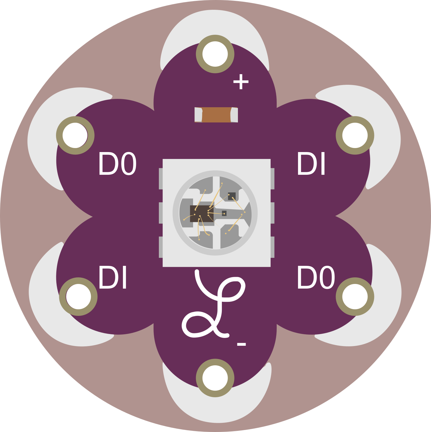
The LilyPad Pixel Board is a versatile and innovative electronic component designed for integrating lighting effects into wearable textiles and e-textiles. It features a 20x20 grid of individually addressable RGB LEDs, providing a canvas for a wide array of colorful patterns and animations. This board is particularly suitable for fashion designers, hobbyists, and educators looking to add an interactive and visual element to their projects.
Explore Projects Built with LilyPad Pixel Board
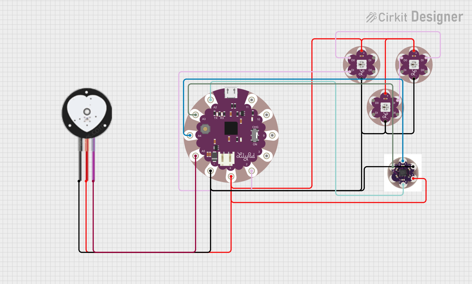

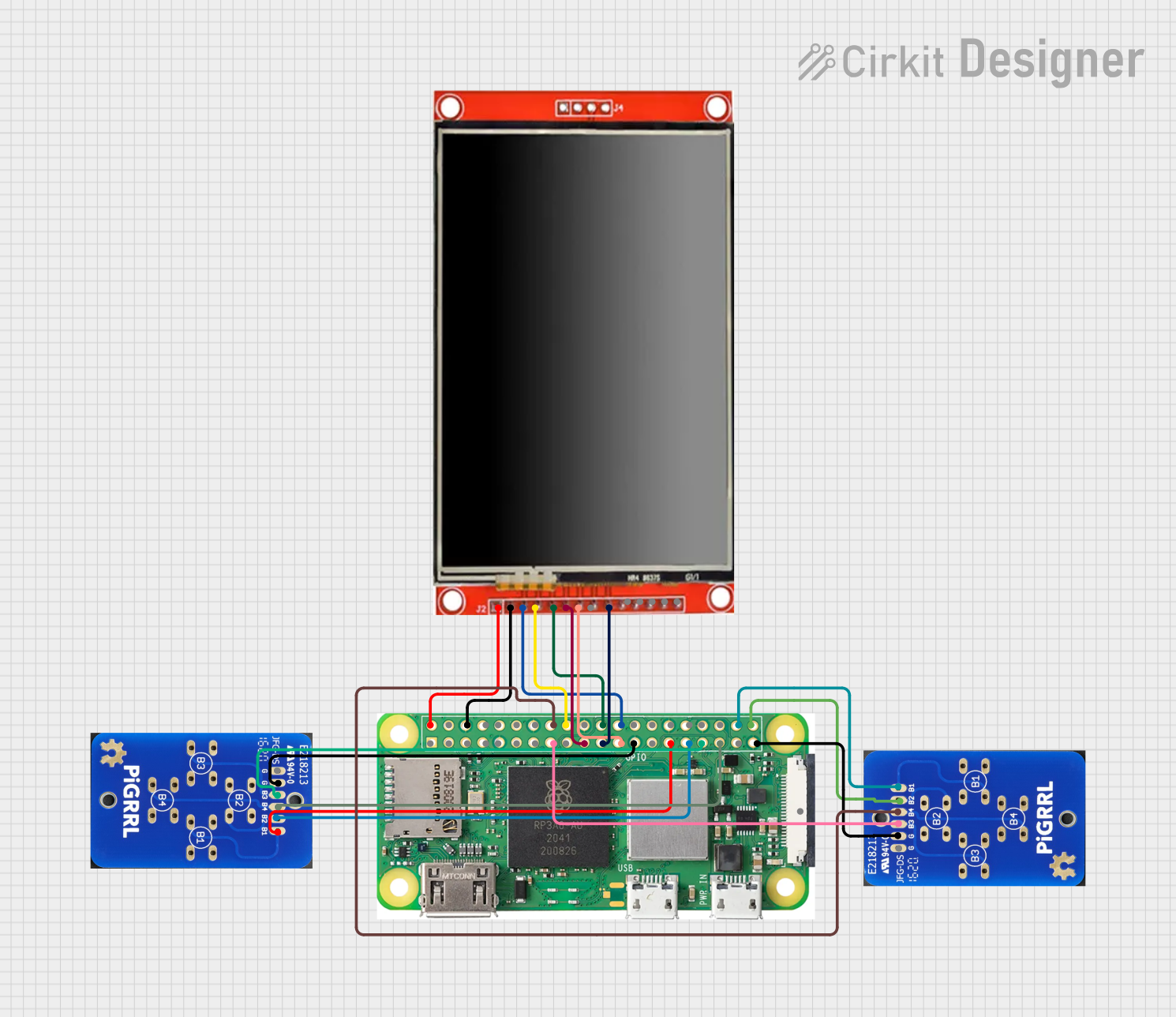

Explore Projects Built with LilyPad Pixel Board
Common Applications and Use Cases
- Wearable electronics (e.g., costumes, interactive clothing)
- Soft circuit projects and educational activities
- Prototyping for fashion technology
- Interactive art installations
Technical Specifications
Key Technical Details
- Supply Voltage: 3.3V to 5V
- Current Rating: Varies based on the number of LEDs lit and their brightness
- Power Consumption: Maximum of 60mA per LED at full brightness
- Communication Protocol: Serial Peripheral Interface (SPI)
- Dimensions: 50mm x 50mm
- Operating Temperature: -10°C to 50°C
Pin Configuration and Descriptions
| Pin Number | Name | Description |
|---|---|---|
| 1 | VCC | Power supply (3.3V to 5V) |
| 2 | GND | Ground connection |
| 3 | DIN | Data input from microcontroller |
| 4 | CIN | Clock input from microcontroller |
| 5 | DOUT | Data output to the next Pixel Board |
| 6 | COUT | Clock output to the next Pixel Board |
Usage Instructions
Integrating with a Circuit
- Power Supply: Connect the VCC pin to a 3.3V to 5V power source and the GND pin to the ground.
- Data and Clock Signals: Connect the DIN and CIN pins to the microcontroller's digital output pins.
- Daisy-Chaining: To control multiple LilyPad Pixel Boards, connect the DOUT and COUT of the first board to the DIN and CIN of the next board, respectively.
Important Considerations and Best Practices
- Ensure the power supply is sufficient for the number of LEDs you plan to use.
- Use current-limiting resistors if necessary to prevent damage to the LEDs.
- Avoid bending the board excessively to prevent damage to the circuitry.
- When sewing the board onto fabric, use conductive thread and secure connections.
Example Code for Arduino UNO
#include <Adafruit_NeoPixel.h>

#define PIN 6 // The pin connected to the DIN on the LilyPad Pixel Board
#define NUMPIXELS 400 // Total number of pixels on the board (20x20)

Adafruit_NeoPixel pixels = Adafruit_NeoPixel(NUMPIXELS, PIN, NEO_GRB + NEO_KHZ800);

void setup() {
  pixels.begin(); // Initialize the pixel board
}

void loop() {
  for(int i = 0; i < NUMPIXELS; i++) {
    pixels.setPixelColor(i, pixels.Color(0,150,0)); // Set color to green
    pixels.show(); // Update the board with set color
    delay(50);
  }
}
Troubleshooting and FAQs
Common Issues
- LEDs Not Lighting Up: Check the power supply and connections to ensure proper voltage and ground are provided. Also, verify that the data and clock pins are correctly connected to the microcontroller.
- Incorrect Colors Displayed: Ensure that the data is being sent in the correct order (GRB for most RGB LEDs) and that the brightness levels are correctly set.
- Dim LEDs: If the LEDs are dimmer than expected, check the power supply for adequate current and consider reducing the number of LEDs lit at one time.
Solutions and Tips for Troubleshooting
- Double-check all connections, especially if the board has been sewn into fabric.
- Use a multimeter to verify that the correct voltage is reaching the board.
- Ensure that the microcontroller's code is correctly uploading and that the correct pin definitions are used.
FAQs
Q: Can I wash the LilyPad Pixel Board? A: The board itself is not waterproof. It should be removed from the fabric before washing, or the fabric should be hand-washed with care to avoid getting the board wet.
Q: How many LilyPad Pixel Boards can I chain together? A: This depends on the power supply's capability and the microcontroller's memory. Each additional board increases the power and memory required to control the LEDs.
Q: What is the maximum brightness for the LEDs? A: The maximum brightness is achieved by setting the color to (255, 255, 255), but this will also increase power consumption. It's important to manage power requirements when using all LEDs at full brightness.