How to Use Rocker Switch: Examples, Pinouts, and Specs
Introduction
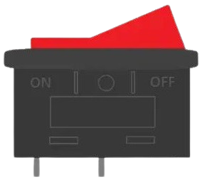
A rocker switch is a type of on/off electrical switch that operates by rocking between two positions. This action either allows the current to flow through the switch or interrupts the circuit, effectively turning the connected device on or off. Rocker switches are commonly used in household appliances, automotive applications, industrial controls, and consumer electronics due to their ease of use and reliability.
Explore Projects Built with Rocker Switch

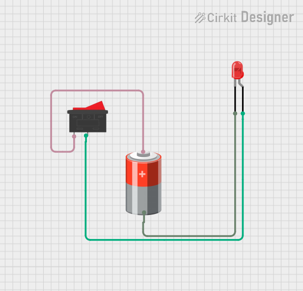
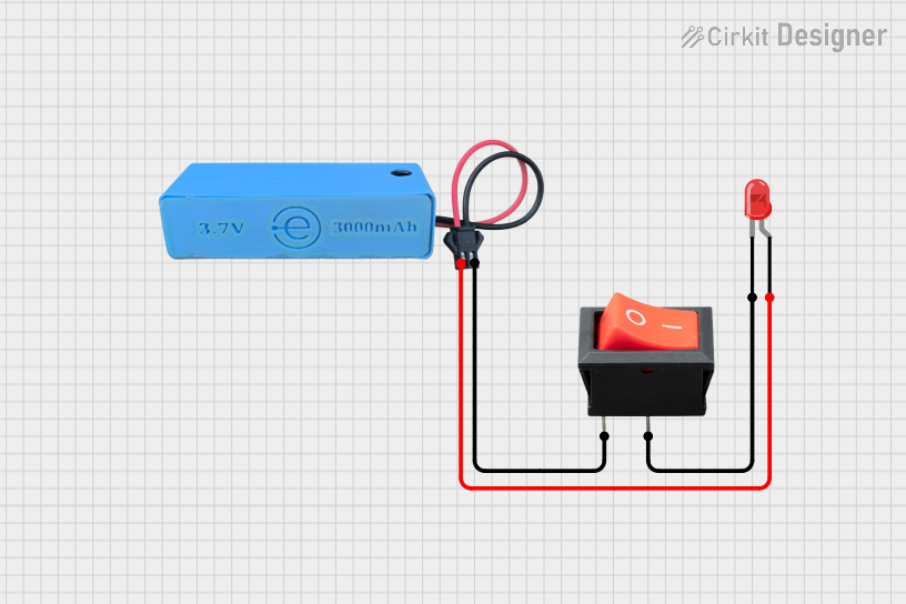
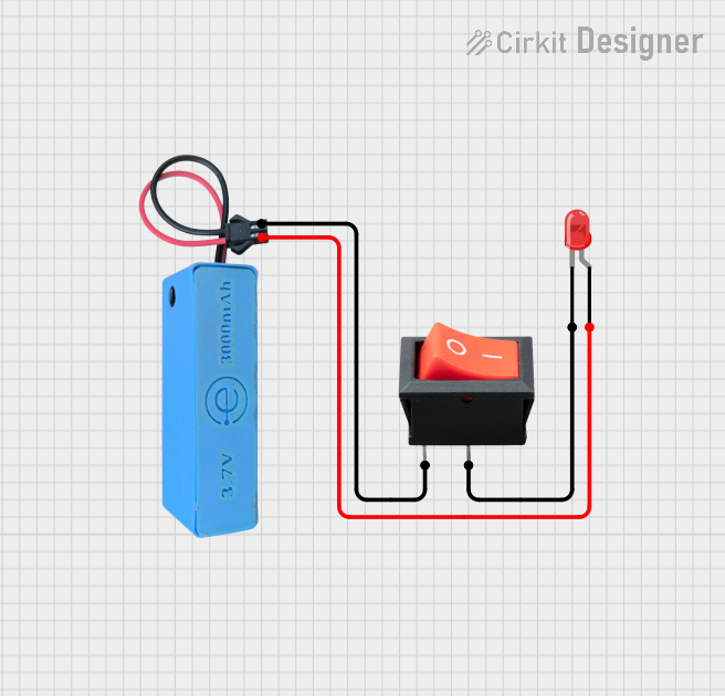
Explore Projects Built with Rocker Switch
Technical Specifications
General Characteristics
- Switch Type: Rocker
- Action: SPST (Single Pole, Single Throw) or DPST (Double Pole, Single Throw), depending on model
- Current Rating: Typically ranges from 3A to 20A
- Voltage Rating: Commonly rated for 120VAC or 250VAC
- Contact Resistance: Varies by model, often less than 50 mΩ
- Insulation Resistance: Typically greater than 100 MΩ
- Dielectric Strength: Usually around 1500VAC for 1 minute
- Operating Temperature: Ranges from -20°C to +85°C
- Mechanical Life: Often rated for 100,000 cycles
- Electrical Life: Typically rated for 10,000 cycles
Pin Configuration and Descriptions
| Pin Number | Description | Notes |
|---|---|---|
| 1 | Input/Line Terminal | Connect to power supply |
| 2 | Output/Load Terminal | Connect to the device or load |
Note: The pin configuration may vary for DPST and other variations of rocker switches.
Usage Instructions
Integration into a Circuit
- Power Off: Ensure that the power supply is turned off before integrating the rocker switch into your circuit.
- Wiring: Connect the input line terminal (Pin 1) to the power supply. The output/load terminal (Pin 2) should be connected to the device or load you wish to control.
- Mounting: Secure the rocker switch in place, typically using the mounting holes provided or snapping it into a panel cutout.
- Testing: Once wired, turn on the power supply and test the switch operation. The device or load should turn on and off as the rocker switch is toggled.
Best Practices
- Use a rocker switch with a current and voltage rating that matches or exceeds the requirements of the connected load.
- Ensure proper insulation of all connections to prevent short circuits.
- If the switch will be exposed to harsh environments, consider using a switch with a higher IP rating for dust and water resistance.
Troubleshooting and FAQs
Common Issues and Solutions
Switch Does Not Operate:
- Check if the power supply is on and properly connected to the switch.
- Inspect the wiring for any loose connections or breaks.
- Verify that the switch is not damaged and is rated appropriately for the load.
Intermittent Operation:
- Tighten any loose connections.
- Replace the switch if it has become worn out or mechanically faulty.
FAQs
Q: Can I use a rocker switch with a DC load? A: Yes, rocker switches can be used with DC loads, but ensure the switch's DC ratings are appropriate for your application.
Q: How do I know if my rocker switch is on or off? A: Many rocker switches have an indicator line or color on one side to signify the "on" position.
Q: Is it safe to change the rocker switch while the power is on? A: It is always recommended to turn off the power before working on electrical components to ensure safety.
Example Code for Arduino UNO
If you're using a rocker switch to control a device with an Arduino UNO, here's a simple example code that demonstrates how to read the state of the rocker switch.
// Define the pin connected to the rocker switch
const int rockerSwitchPin = 2;

void setup() {
  // Set the rocker switch pin as an input
  pinMode(rockerSwitchPin, INPUT);
  // Initialize serial communication at 9600 bits per second
  Serial.begin(9600);
}

void loop() {
  // Read the state of the rocker switch
  int switchState = digitalRead(rockerSwitchPin);

  // Print the state of the switch to the Serial Monitor
  Serial.println(switchState);

  // Add a small delay to prevent bouncing issues
  delay(50);
}
Note: In this example, the rocker switch is connected to digital pin 2. One terminal of the switch is connected to the pin, and the other terminal is connected to ground. The internal pull-up resistor is used to ensure a default high state when the switch is open.