How to Use Modulo Mini Interruptor Magnetico: Examples, Pinouts, and Specs
Introduction
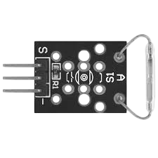
The Modulo Mini Interruptor Magnetico (KY21), manufactured by Keys, is a compact magnetic switch module designed to detect the presence of a magnetic field. This module is widely used in security systems, such as door and window sensors, to detect when a door or window is opened or closed. It is also suitable for other applications requiring magnetic field detection, such as proximity sensing and automation systems.
Explore Projects Built with Modulo Mini Interruptor Magnetico


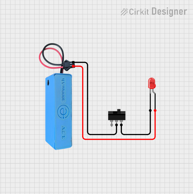
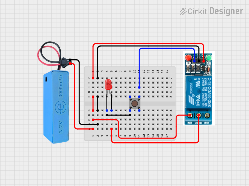
Explore Projects Built with Modulo Mini Interruptor Magnetico
Common Applications:
- Security systems (e.g., door/window sensors)
- Proximity detection in industrial automation
- Magnetic field detection in DIY electronics projects
- Smart home systems for monitoring doors and windows
Technical Specifications
The following table outlines the key technical details of the KY21 module:
| Parameter | Value |
|---|---|
| Operating Voltage | 3.3V to 5V |
| Operating Current | < 5mA |
| Output Type | Digital (High/Low) |
| Detection Range | 10mm to 20mm (depending on magnet strength) |
| Dimensions | 32mm x 14mm x 10mm |
| Operating Temperature | -20°C to 70°C |
Pin Configuration and Descriptions
The KY21 module has three pins, as described in the table below:
| Pin | Name | Description |
|---|---|---|
| 1 | VCC | Power supply input (3.3V to 5V) |
| 2 | GND | Ground connection |
| 3 | OUT | Digital output pin (HIGH when no magnet is detected, LOW when a magnet is detected) |
Usage Instructions
How to Use the KY21 in a Circuit
- Power the Module: Connect the
VCCpin to a 3.3V or 5V power source and theGNDpin to the ground of your circuit. - Connect the Output: Connect the
OUTpin to a digital input pin of your microcontroller or to another circuit that requires the magnetic field detection signal. - Place the Magnet: Position a magnet near the module. When the magnet is within the detection range, the
OUTpin will go LOW. When the magnet is removed, theOUTpin will return to HIGH.
Important Considerations and Best Practices
- Magnet Strength: Ensure the magnet used is strong enough to be detected within the desired range.
- Placement: Avoid placing the module near strong electromagnetic interference (EMI) sources, as this may affect its performance.
- Debouncing: If using the module with a microcontroller, consider implementing software debouncing to handle any noise or fluctuations in the output signal.
Example: Connecting the KY21 to an Arduino UNO
Below is an example of how to connect and use the KY21 module with an Arduino UNO:
Circuit Connections:
- Connect the
VCCpin of the KY21 to the 5V pin of the Arduino. - Connect the
GNDpin of the KY21 to the GND pin of the Arduino. - Connect the
OUTpin of the KY21 to digital pin 2 of the Arduino.
Arduino Code:
// KY21 Magnetic Switch Module Example
// This code reads the output of the KY21 module and prints the status to the Serial Monitor.

const int sensorPin = 2; // KY21 OUT pin connected to digital pin 2
int sensorState = 0;     // Variable to store the sensor state

void setup() {
  pinMode(sensorPin, INPUT); // Set the sensor pin as input
  Serial.begin(9600);        // Initialize serial communication at 9600 baud
}

void loop() {
  sensorState = digitalRead(sensorPin); // Read the state of the sensor

  if (sensorState == LOW) {
    // Magnet is detected
    Serial.println("Magnet detected!");
  } else {
    // Magnet is not detected
    Serial.println("No magnet detected.");
  }

  delay(500); // Wait for 500ms before reading again
}
Troubleshooting and FAQs
Common Issues and Solutions
The module does not detect the magnet:
- Solution: Ensure the magnet is within the detection range (10mm to 20mm). Use a stronger magnet if necessary.
- Solution: Verify that the module is powered correctly (3.3V to 5V) and that all connections are secure.
The output signal is unstable:
- Solution: Check for sources of electromagnetic interference (EMI) near the module and relocate it if needed.
- Solution: Add a capacitor (e.g., 0.1µF) across the power supply pins to filter noise.
The module outputs a constant HIGH signal:
- Solution: Ensure the magnet is not too far from the module. Test with a different magnet if needed.
- Solution: Verify that the
OUTpin is properly connected to the microcontroller or circuit.
FAQs
Q: Can the KY21 module detect any type of magnet?
A: Yes, the KY21 can detect most types of magnets, but the detection range depends on the magnet's strength and size.
Q: Can I use the KY21 with a 3.3V microcontroller?
A: Yes, the KY21 operates within a voltage range of 3.3V to 5V, making it compatible with 3.3V microcontrollers like the ESP32.
Q: Is the KY21 suitable for outdoor use?
A: The KY21 is not waterproof or weatherproof. If used outdoors, it should be enclosed in a protective casing to prevent damage from moisture or dust.