
How to Use Adafruit DS3231 STEMMA QT: Examples, Pinouts, and Specs
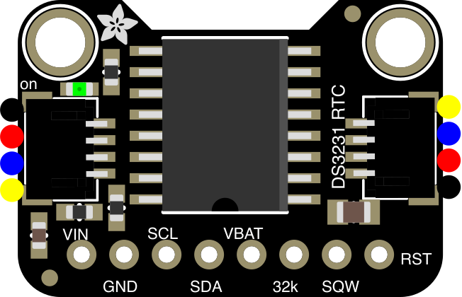
 Design with Adafruit DS3231 STEMMA QT in Cirkit Designer
Introduction
The Adafruit DS3231 STEMMA QT (Part ID: 5188) is a high-precision real-time clock (RTC) module designed for accurate timekeeping. It is based on the DS3231 chip, which features an integrated temperature-compensated crystal oscillator (TCXO) to maintain precise time even under varying environmental conditions. The module communicates via an I2C interface, making it easy to integrate with microcontrollers such as Arduino, Raspberry Pi, and others. Additionally, it includes a built-in temperature sensor for added functionality.
Explore Projects Built with Adafruit DS3231 STEMMA QT
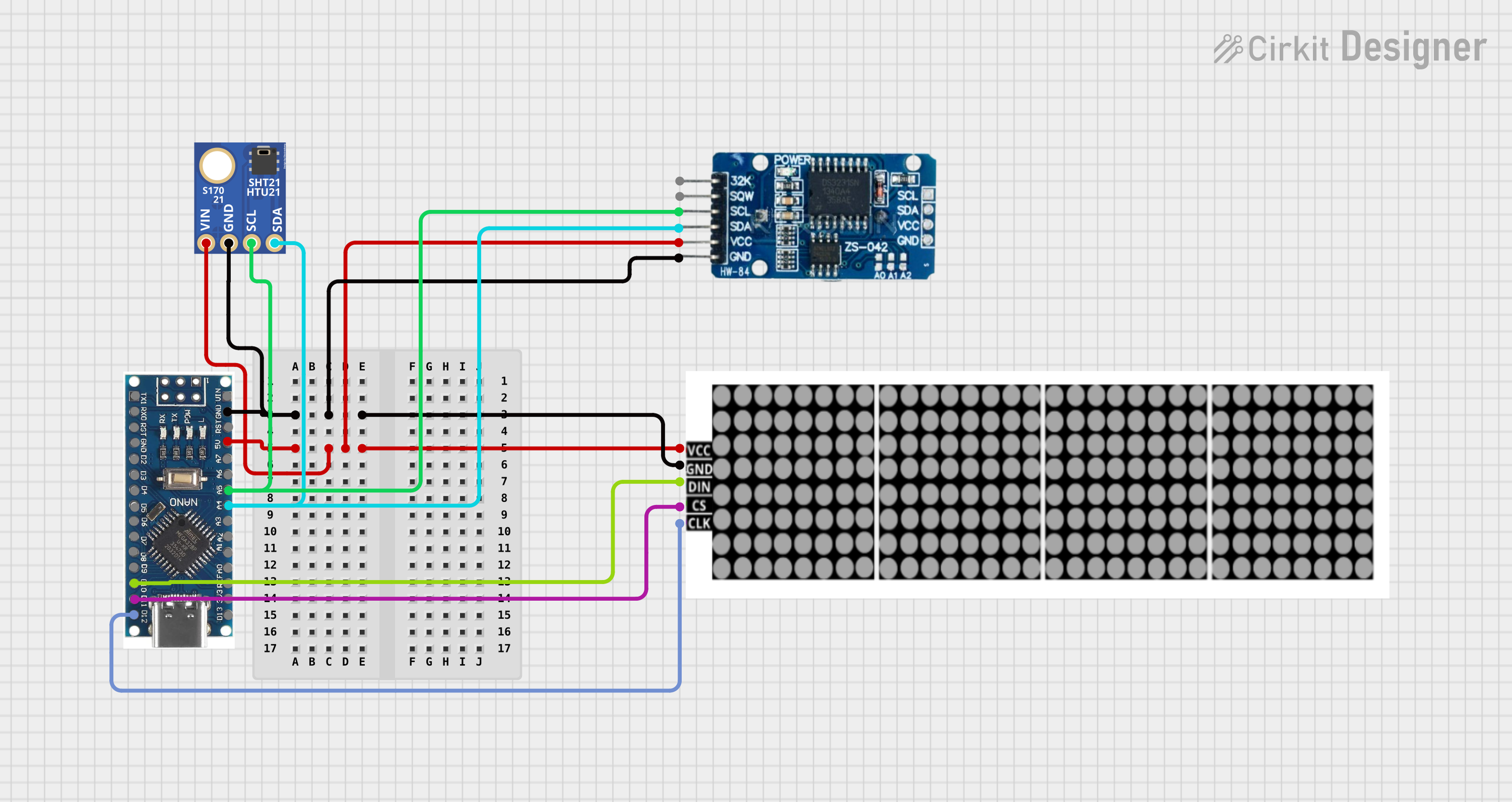 Open Project in Cirkit Designer
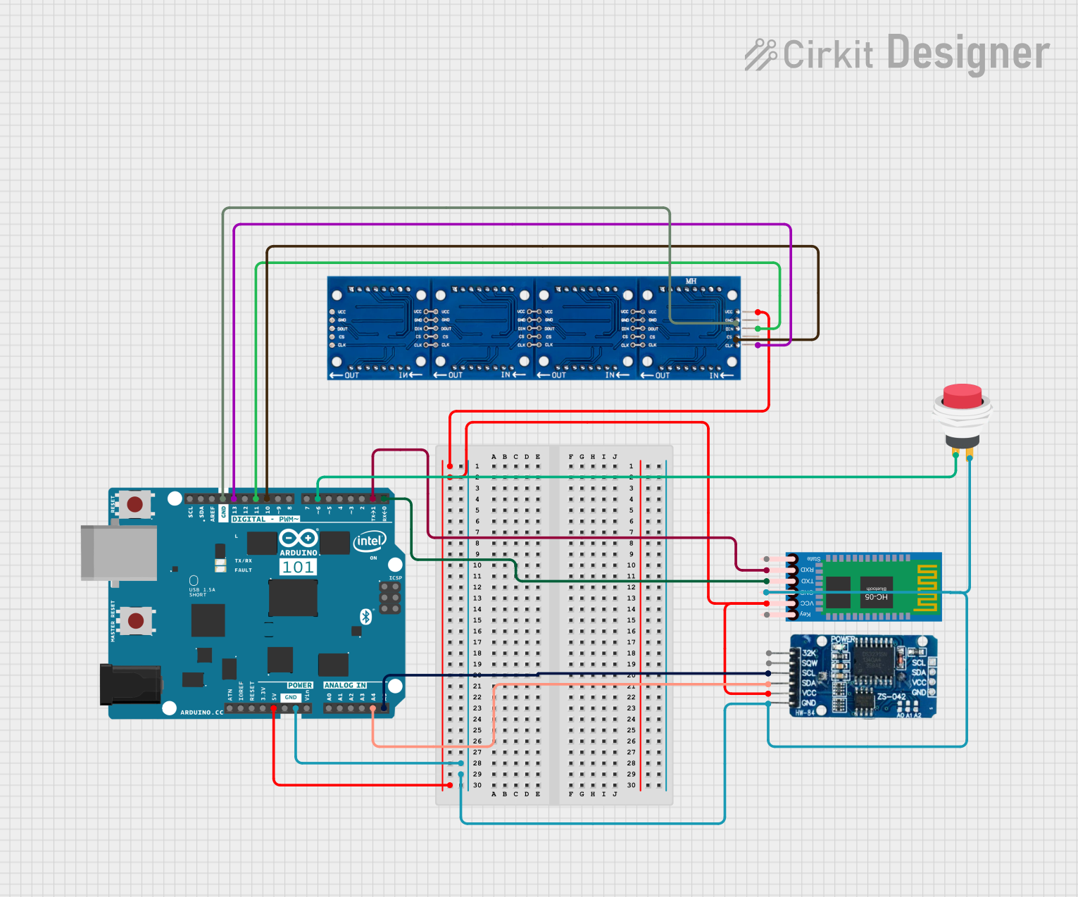 Open Project in Cirkit Designer
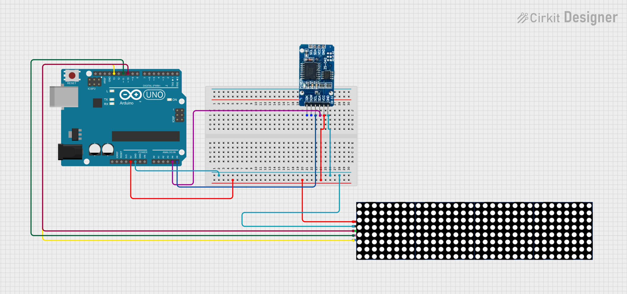 Open Project in Cirkit Designer
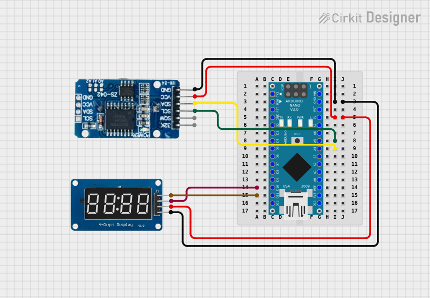 Open Project in Cirkit Designer
Explore Projects Built with Adafruit DS3231 STEMMA QT
Open Project in Cirkit DesignerOpen Project in Cirkit DesignerOpen Project in Cirkit DesignerOpen Project in Cirkit DesignerCommon Applications and Use Cases
- Timekeeping for data logging applications
- Scheduling and automation systems
- Alarms and timers
- Temperature monitoring
- Low-power devices requiring accurate timekeeping during power outages (with battery backup)
Technical Specifications
Below are the key technical details of the Adafruit DS3231 STEMMA QT module:
| Parameter | Value |
|---|---|
| Chip | DS3231 |
| Interface | I2C (2-wire) |
| Operating Voltage | 3.3V to 5V |
| Current Consumption | ~200 µA (active), ~3 µA (battery backup) |
| Timekeeping Accuracy | ±2 ppm (0°C to +40°C), ±3.5 ppm (-40°C to +85°C) |
| Temperature Sensor Range | -40°C to +85°C |
| Temperature Sensor Accuracy | ±3°C |
| Backup Battery Support | CR1220 coin cell (not included) |
| Dimensions | 25mm x 25mm x 5mm |
Pin Configuration and Descriptions
The Adafruit DS3231 STEMMA QT module has the following pinout:
| Pin | Name | Description |
|---|---|---|
| 1 | VIN | Power input (3.3V to 5V) |
| 2 | GND | Ground connection |
| 3 | SDA | I2C data line |
| 4 | SCL | I2C clock line |
| 5 | STEMMA QT | I2C quick-connect ports for daisy-chaining multiple I2C devices (2 connectors) |
Usage Instructions
How to Use the Component in a Circuit
- Power the Module: Connect the VIN pin to a 3.3V or 5V power source and the GND pin to ground.
- Connect I2C Lines: Connect the SDA and SCL pins to the corresponding I2C pins on your microcontroller. For Arduino UNO:
- SDA connects to A4
- SCL connects to A5
- Optional Battery Backup: Insert a CR1220 coin cell battery into the battery holder to maintain timekeeping during power loss.
- Daisy-Chaining: Use the STEMMA QT connectors to easily chain multiple I2C devices.
Important Considerations and Best Practices
- Ensure the I2C pull-up resistors are present on the bus. Most microcontrollers include these by default.
- Avoid exceeding the operating voltage range (3.3V to 5V) to prevent damage to the module.
- Use a CR1220 battery for backup power to maintain timekeeping during power outages.
- The I2C address of the DS3231 is
0x68by default. Ensure no other devices on the I2C bus share this address.
Example Code for Arduino UNO
Below is an example of how to use the Adafruit DS3231 STEMMA QT module with an Arduino UNO. This code reads the current time and temperature from the module.
#include <Wire.h>
#include "RTClib.h" // Adafruit RTC library

RTC_DS3231 rtc; // Create an RTC object

void setup() {
  Serial.begin(9600); // Initialize serial communication
  Wire.begin();       // Initialize I2C communication

  if (!rtc.begin()) {
    Serial.println("Couldn't find RTC. Check connections!");
    while (1); // Halt execution if RTC is not found
  }

  if (rtc.lostPower()) {
    Serial.println("RTC lost power, setting the time!");
    // Set the RTC to the current date and time
    rtc.adjust(DateTime(F(__DATE__), F(__TIME__)));
  }
}

void loop() {
  DateTime now = rtc.now(); // Get the current date and time

  // Print the current date and time
  Serial.print("Date: ");
  Serial.print(now.year(), DEC);
  Serial.print('/');
  Serial.print(now.month(), DEC);
  Serial.print('/');
  Serial.print(now.day(), DEC);
  Serial.print(" Time: ");
  Serial.print(now.hour(), DEC);
  Serial.print(':');
  Serial.print(now.minute(), DEC);
  Serial.print(':');
  Serial.println(now.second(), DEC);

  // Read and print the temperature
  float temperature = rtc.getTemperature();
  Serial.print("Temperature: ");
  Serial.print(temperature);
  Serial.println(" °C");

  delay(1000); // Wait 1 second before repeating
}
Troubleshooting and FAQs
Common Issues and Solutions
RTC Not Detected
- Cause: Incorrect wiring or I2C address conflict.
- Solution: Verify the SDA and SCL connections. Ensure no other devices on the I2C bus use the
0x68address.
Incorrect Time
- Cause: RTC lost power or was not initialized properly.
- Solution: Check the backup battery. Use the
rtc.adjust()function to set the correct time.
Temperature Readings Seem Inaccurate
- Cause: Operating outside the specified temperature range or environmental interference.
- Solution: Ensure the module is within the -40°C to +85°C range. Avoid placing the module near heat sources.
Module Not Responding
- Cause: Insufficient power supply or damaged module.
- Solution: Verify the power supply voltage (3.3V to 5V). Check for physical damage to the module.
FAQs
Can I use the module with a 3.3V microcontroller? Yes, the module supports both 3.3V and 5V logic levels.
What happens if the backup battery is not installed? The RTC will lose timekeeping during power outages but will function normally when powered.
Can I use multiple DS3231 modules on the same I2C bus? No, the DS3231 has a fixed I2C address (
0x68), so only one module can be used per I2C bus.How accurate is the timekeeping? The DS3231 maintains an accuracy of ±2 ppm from 0°C to +40°C, equivalent to about ±1 minute per year.