
How to Use GND_CONNECT: Examples, Pinouts, and Specs
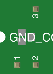
 Design with GND_CONNECT in Cirkit Designer
Introduction
The GND_CONNECT is a ground connection point in an electronic circuit. It serves as a common return path for electric current and helps stabilize voltage levels across the circuit. Ground connections are essential in ensuring proper circuit operation, reducing noise, and providing a reference point for voltage measurements.
Explore Projects Built with GND_CONNECT
 Open Project in Cirkit Designer
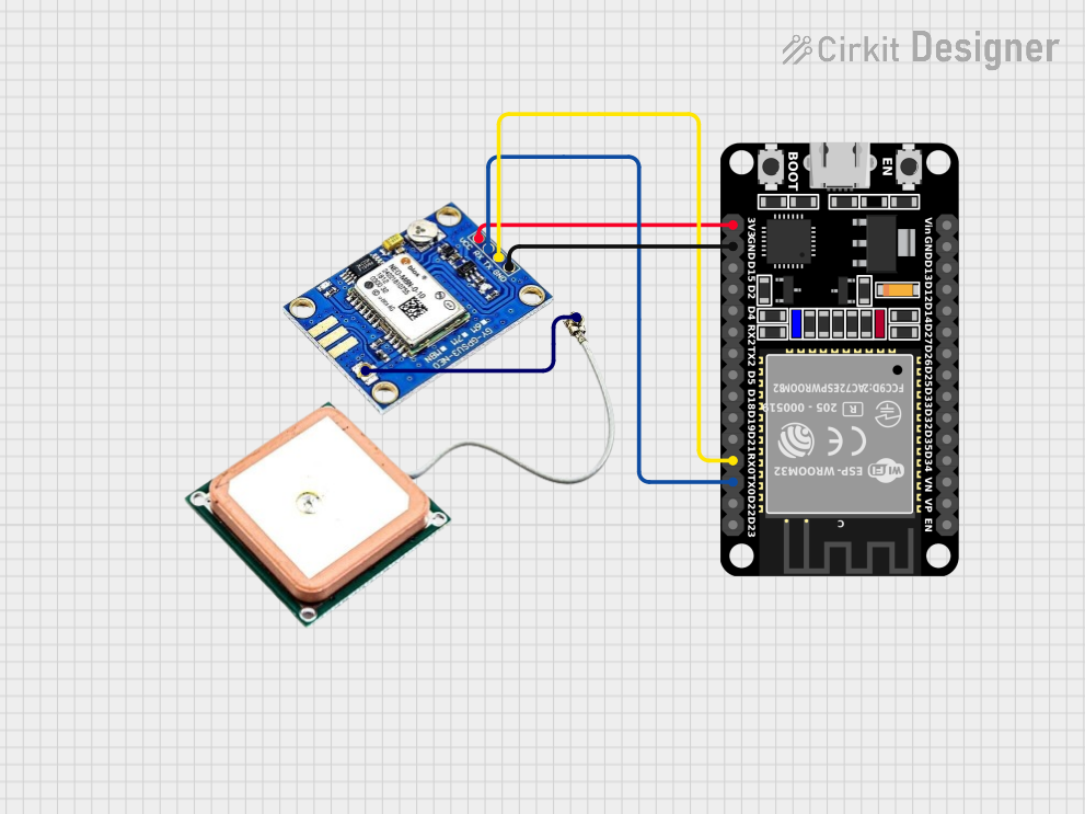 Open Project in Cirkit Designer
 Open Project in Cirkit Designer
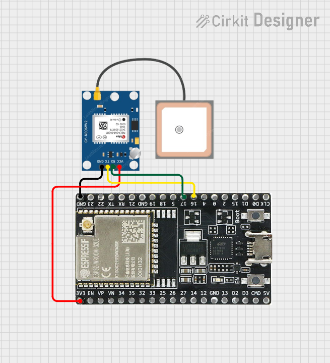 Open Project in Cirkit Designer
Explore Projects Built with GND_CONNECT
Open Project in Cirkit DesignerOpen Project in Cirkit DesignerOpen Project in Cirkit DesignerOpen Project in Cirkit DesignerCommon Applications and Use Cases
- Used in all types of electronic circuits to establish a common ground.
- Provides a stable reference point for analog and digital signals.
- Essential for reducing electromagnetic interference (EMI) and noise in circuits.
- Used in PCB designs, breadboards, and prototyping setups.
Technical Specifications
The GND_CONNECT is not an active component but a critical part of circuit design. Below are its key characteristics:
Key Technical Details
- Type: Passive connection point
- Voltage Rating: Supports the circuit's operating voltage (e.g., 3.3V, 5V, 12V, etc.)
- Current Rating: Depends on the wire or PCB trace connected to the ground point
- Impedance: Ideally 0Ω (practically very low resistance)
Pin Configuration and Descriptions
The GND_CONNECT does not have a standard pinout but is typically represented as a symbol in schematics or a physical connection point in circuits. Below is an example of how it might appear in different contexts:
| Pin/Connection | Description |
|---|---|
| GND | Ground connection point. Provides a common return path for current in the circuit. |
Usage Instructions
How to Use the Component in a Circuit
- Identify the Ground Symbol: In circuit schematics, the ground is typically represented by a downward-pointing triangle or a horizontal line with three descending lines.
- Connect All Ground Points: Ensure all components requiring a ground connection are linked to the same ground point to maintain a common reference.
- Use Proper Wiring: For breadboards, use black wires to connect components to the ground rail. On PCBs, ensure the ground plane is continuous and has low resistance.
- Avoid Ground Loops: Ensure there is only one ground reference point to prevent unwanted current paths and noise.
Important Considerations and Best Practices
- Ground Plane Design: In PCB layouts, use a solid ground plane to minimize resistance and improve signal integrity.
- Star Grounding: For high-power circuits, use a star grounding technique to prevent ground loops.
- Decoupling Capacitors: Place decoupling capacitors near ICs to stabilize voltage levels and reduce noise.
- Arduino UNO Example: When using an Arduino UNO, connect the GND pin of the Arduino to the ground rail of your circuit.
Example Arduino UNO Circuit
Below is an example of connecting an LED to an Arduino UNO with a ground connection:
// Example: Blinking an LED with proper ground connection

int ledPin = 13; // Pin connected to the LED

void setup() {
  pinMode(ledPin, OUTPUT); // Set the LED pin as an output
}

void loop() {
  digitalWrite(ledPin, HIGH); // Turn the LED on
  delay(1000);               // Wait for 1 second
  digitalWrite(ledPin, LOW);  // Turn the LED off
  delay(1000);               // Wait for 1 second
}

// Ensure the GND pin of the Arduino is connected to the ground rail
// of the circuit. This provides a common return path for current.
Troubleshooting and FAQs
Common Issues Users Might Face
- No Voltage Reference: If the ground is not properly connected, components may not function correctly due to a lack of a stable voltage reference.
- Ground Loops: Multiple ground points can create loops, leading to noise and interference.
- High Resistance in Ground Path: Poor connections or thin wires can increase resistance, causing voltage drops.
Solutions and Tips for Troubleshooting
- Check Connections: Ensure all ground connections are secure and continuous.
- Use a Multimeter: Measure resistance between ground points to ensure it is close to 0Ω.
- Inspect PCB Layout: Verify that the ground plane is uninterrupted and properly connected.
- Avoid Long Ground Wires: Use short, thick wires for ground connections to reduce resistance and inductance.
By following these guidelines, the GND_CONNECT can be effectively used to ensure stable and reliable circuit operation.