Cirkit Designer Logo
Cirkit Designer
Your all-in-one circuit design IDE
Home / 
Component Documentation

How to Use S8V9F5: Examples, Pinouts, and Specs

Image of S8V9F5
Cirkit Designer LogoDesign with S8V9F5 in Cirkit Designer

Introduction

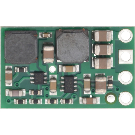
The S8V9F5 is a high-performance DC-DC step-up/step-down voltage regulator manufactured by Pololu. This versatile component is designed to efficiently regulate voltage in a wide range of electronic applications. It can step up or step down the input voltage to provide a stable output, making it ideal for systems where the input voltage may vary above or below the desired output voltage.

Explore Projects Built with S8V9F5

Use Cirkit Designer to design, explore, and prototype these projects online. Some projects support real-time simulation. Click "Open Project" to start designing instantly!
Battery-Powered Emergency Alert System with NUCLEO-F072RB, SIM800L, and GPS NEO 6M
Image of women safety: A project utilizing S8V9F5 in a practical application
This circuit is an emergency alert system that uses a NUCLEO-F072RB microcontroller to send SMS alerts and make calls via a SIM800L GSM module, while obtaining location data from a GPS NEO 6M module. The system is powered by a Li-ion battery and includes a TP4056 module for battery charging and protection, with a rocker switch to control power to the microcontroller.
Cirkit Designer LogoOpen Project in Cirkit Designer
Arduino UNO with A9G GSM/GPRS and Dual VL53L1X Distance Sensors
Image of TED CIRCUIT : A project utilizing S8V9F5 in a practical application
This circuit features an Arduino UNO microcontroller interfaced with an A9G GSM/GPRS+GPS/BDS module and two VL53L1X time-of-flight distance sensors. The A9G module is connected to the Arduino via serial communication for GPS and GSM functionalities, while both VL53L1X sensors are connected through I2C with shared SDA and SCL lines and individual SHUT pins for selective sensor activation. The Arduino is programmed to control these peripherals, although the specific functionality is not detailed in the provided code.
Cirkit Designer LogoOpen Project in Cirkit Designer
NFC-Enabled Access Control System with Time Logging
Image of doorlock: A project utilizing S8V9F5 in a practical application
This circuit is designed for access control with time tracking capabilities. It features an NFC/RFID reader for authentication, an RTC module (DS3231) for real-time clock functionality, and an OLED display for user interaction. A 12V relay controls a magnetic lock, which is activated upon successful NFC/RFID authentication, and a button switch is likely used for manual operation or input. The T8_S3 microcontroller serves as the central processing unit, interfacing with the NFC/RFID reader, RTC, OLED, and relay to manage the access control logic.
Cirkit Designer LogoOpen Project in Cirkit Designer
ESP32-Controlled Multi-Display Interactive System with Pushbutton Inputs
Image of ORBS: A project utilizing S8V9F5 in a practical application
This circuit consists of multiple GC9A01 display modules interfaced with an ESP32 microcontroller. The ESP32 controls the reset (RST), chip select (CS), data/command (DC), serial data (SDA), and serial clock (SCL) lines of each display, allowing for individual communication with each screen. Additionally, there are pushbuttons connected to the ESP32, which could be used for user input to control the displays or other functions within the circuit.
Cirkit Designer LogoOpen Project in Cirkit Designer

Explore Projects Built with S8V9F5

Use Cirkit Designer to design, explore, and prototype these projects online. Some projects support real-time simulation. Click "Open Project" to start designing instantly!
Image of women safety: A project utilizing S8V9F5 in a practical application
Battery-Powered Emergency Alert System with NUCLEO-F072RB, SIM800L, and GPS NEO 6M
This circuit is an emergency alert system that uses a NUCLEO-F072RB microcontroller to send SMS alerts and make calls via a SIM800L GSM module, while obtaining location data from a GPS NEO 6M module. The system is powered by a Li-ion battery and includes a TP4056 module for battery charging and protection, with a rocker switch to control power to the microcontroller.
Cirkit Designer LogoOpen Project in Cirkit Designer
Image of TED CIRCUIT : A project utilizing S8V9F5 in a practical application
Arduino UNO with A9G GSM/GPRS and Dual VL53L1X Distance Sensors
This circuit features an Arduino UNO microcontroller interfaced with an A9G GSM/GPRS+GPS/BDS module and two VL53L1X time-of-flight distance sensors. The A9G module is connected to the Arduino via serial communication for GPS and GSM functionalities, while both VL53L1X sensors are connected through I2C with shared SDA and SCL lines and individual SHUT pins for selective sensor activation. The Arduino is programmed to control these peripherals, although the specific functionality is not detailed in the provided code.
Cirkit Designer LogoOpen Project in Cirkit Designer
Image of doorlock: A project utilizing S8V9F5 in a practical application
NFC-Enabled Access Control System with Time Logging
This circuit is designed for access control with time tracking capabilities. It features an NFC/RFID reader for authentication, an RTC module (DS3231) for real-time clock functionality, and an OLED display for user interaction. A 12V relay controls a magnetic lock, which is activated upon successful NFC/RFID authentication, and a button switch is likely used for manual operation or input. The T8_S3 microcontroller serves as the central processing unit, interfacing with the NFC/RFID reader, RTC, OLED, and relay to manage the access control logic.
Cirkit Designer LogoOpen Project in Cirkit Designer
Image of ORBS: A project utilizing S8V9F5 in a practical application
ESP32-Controlled Multi-Display Interactive System with Pushbutton Inputs
This circuit consists of multiple GC9A01 display modules interfaced with an ESP32 microcontroller. The ESP32 controls the reset (RST), chip select (CS), data/command (DC), serial data (SDA), and serial clock (SCL) lines of each display, allowing for individual communication with each screen. Additionally, there are pushbuttons connected to the ESP32, which could be used for user input to control the displays or other functions within the circuit.
Cirkit Designer LogoOpen Project in Cirkit Designer

Common Applications and Use Cases

  • Battery-powered devices where the input voltage fluctuates (e.g., lithium-ion batteries)
  • Robotics and embedded systems requiring stable voltage
  • Portable electronics and IoT devices
  • Powering microcontrollers, sensors, and communication modules
  • Applications requiring protection against overcurrent and thermal overload

Technical Specifications

Key Technical Details

  • Input Voltage Range: 2.8 V to 32 V
  • Output Voltage: Fixed at 5 V
  • Maximum Output Current: Up to 2 A (depending on input voltage)
  • Efficiency: Up to 90% (varies with input/output conditions)
  • Quiescent Current: Approximately 1 mA
  • Built-in Protections:
    • Overcurrent protection
    • Thermal shutdown
  • Operating Temperature Range: -40°C to +85°C
  • Dimensions: 12.7 mm × 12.7 mm × 3.8 mm
  • Weight: 1.2 g

Pin Configuration and Descriptions

The S8V9F5 module has six pins. Below is the pinout and description:

Pin Name Pin Number Description
VIN 1 Input voltage pin (2.8 V to 32 V). Connect to the positive terminal of the power source.
GND 2, 5 Ground pins. Connect to the negative terminal of the power source.
VOUT 3 Regulated output voltage pin (5 V). Connect to the load.
SHDN 4 Shutdown pin. Drive low to disable the regulator; leave floating or drive high to enable.
PG 6 Power good indicator. Outputs a high signal when the output voltage is stable.

Usage Instructions

How to Use the S8V9F5 in a Circuit

  1. Power Connections:

    • Connect the VIN pin to the positive terminal of your power source (e.g., battery or DC supply).
    • Connect the GND pins to the negative terminal of your power source.
    • Ensure the input voltage is within the range of 2.8 V to 32 V.
  2. Output Connections:

    • Connect the VOUT pin to your load. The output voltage is fixed at 5 V.
  3. Enable/Disable Functionality:

    • To enable the regulator, leave the SHDN pin floating or drive it high.
    • To disable the regulator, drive the SHDN pin low.
  4. Power Good Indicator:

    • Use the PG pin to monitor the output voltage. A high signal indicates that the output voltage is stable.

Important Considerations and Best Practices

  • Input Capacitor: Place a low-ESR capacitor (e.g., 10 µF) close to the VIN pin to reduce input voltage ripple.
  • Output Capacitor: Use a low-ESR capacitor (e.g., 10 µF) near the VOUT pin to stabilize the output voltage.
  • Thermal Management: Ensure adequate ventilation or heat dissipation if operating near the maximum current limit.
  • Wiring: Keep the input and output wires as short as possible to minimize noise and voltage drops.
  • Load Current: The maximum output current depends on the input voltage. Refer to the efficiency and current graphs in the Pololu datasheet for detailed performance data.

Example: Using the S8V9F5 with an Arduino UNO

The S8V9F5 can be used to power an Arduino UNO from a variable power source. Below is an example circuit and Arduino code to monitor the PG pin.

Circuit Diagram

  1. Connect the VIN pin to a 9 V battery.
  2. Connect the GND pin to the battery's negative terminal and the Arduino's GND pin.
  3. Connect the VOUT pin to the Arduino's 5 V pin.
  4. Connect the PG pin to Arduino digital pin 2.

Arduino Code

// Define the pin connected to the PG (Power Good) signal
const int pgPin = 2;

void setup() {
  // Initialize serial communication for debugging
  Serial.begin(9600);

  // Set the PG pin as an input
  pinMode(pgPin, INPUT);

  // Print a startup message
  Serial.println("S8V9F5 Power Good Monitoring Started");
}

void loop() {
  // Read the state of the PG pin
  int pgState = digitalRead(pgPin);

  // Check if the output voltage is stable
  if (pgState == HIGH) {
    Serial.println("Output voltage is stable (Power Good).");
  } else {
    Serial.println("Output voltage is not stable!");
  }

  // Wait for 1 second before checking again
  delay(1000);
}

Troubleshooting and FAQs

Common Issues and Solutions

  1. No Output Voltage:

    • Ensure the SHDN pin is not driven low. Leave it floating or drive it high.
    • Verify that the input voltage is within the specified range (2.8 V to 32 V).
    • Check for loose or incorrect connections.
  2. Output Voltage is Unstable:

    • Add low-ESR capacitors to the input and output pins as recommended.
    • Ensure the load does not exceed the maximum current rating.
  3. Component Overheating:

    • Reduce the load current if operating near the maximum limit.
    • Improve ventilation or add a heatsink if necessary.
  4. PG Pin Always Low:

    • Verify that the output voltage is within the expected range.
    • Check the wiring and ensure the load is properly connected.

FAQs

Q1: Can the S8V9F5 output a voltage other than 5 V?
No, the S8V9F5 is a fixed 5 V regulator. For adjustable output voltages, consider other Pololu regulators.

Q2: What happens if the input voltage exceeds 32 V?
The regulator may be damaged. Always ensure the input voltage stays within the specified range.

Q3: Can I use the S8V9F5 with a rechargeable battery?
Yes, the S8V9F5 is ideal for battery-powered applications, as it can handle varying input voltages.

Q4: Is reverse polarity protection included?
No, the S8V9F5 does not have built-in reverse polarity protection. Use an external diode to protect the circuit.

Q5: How do I calculate efficiency for my application?
Refer to the efficiency graphs in the Pololu datasheet. Efficiency depends on the input voltage, output voltage, and load current.