How to Use Mini 3A DC-DC Buck Convertor: Examples, Pinouts, and Specs
Introduction
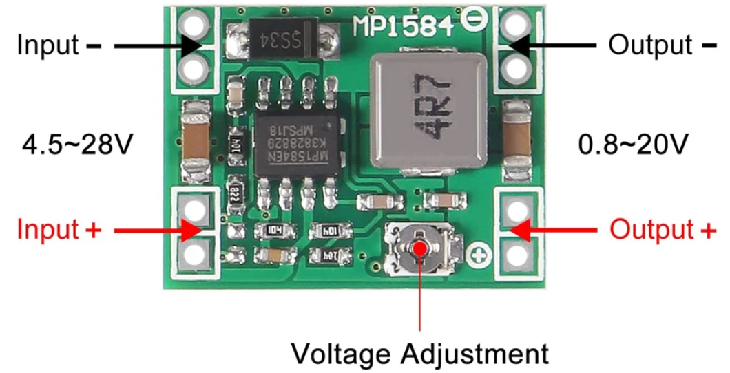
The Mini 3A DC-DC Buck Converter (DZS IP1584) is a compact and efficient step-down voltage regulator designed to convert a higher DC input voltage to a lower DC output voltage. It is based on the IP1584 chip and is capable of delivering up to 3A of output current with high efficiency, making it ideal for a wide range of power supply applications.
Explore Projects Built with Mini 3A DC-DC Buck Convertor


Explore Projects Built with Mini 3A DC-DC Buck Convertor
Common Applications and Use Cases
- Powering low-voltage devices from higher-voltage sources (e.g., 12V to 5V conversion)
- Battery-powered systems to regulate voltage
- DIY electronics projects and prototyping
- Arduino and microcontroller-based applications
- LED drivers and portable devices
Technical Specifications
Below are the key technical details of the Mini 3A DC-DC Buck Converter:
| Parameter | Value |
|---|---|
| Input Voltage Range | 4.5V to 28V |
| Output Voltage Range | 0.8V to 20V (adjustable via potentiometer) |
| Maximum Output Current | 3A |
| Efficiency | Up to 92% |
| Switching Frequency | 150 kHz |
| Operating Temperature | -40°C to +85°C |
| Dimensions | 22mm x 17mm x 4mm |
Pin Configuration and Descriptions
The Mini 3A DC-DC Buck Converter has the following pinout:
| Pin Name | Description |
|---|---|
| VIN | Input voltage pin (connect to the higher DC voltage) |
| VOUT | Output voltage pin (connect to the load) |
| GND | Ground pin (common ground for input and output) |
Usage Instructions
How to Use the Component in a Circuit
Connect the Input Voltage (VIN):
- Attach the positive terminal of your DC power source to the
VINpin. - Connect the negative terminal of your power source to the
GNDpin.
- Attach the positive terminal of your DC power source to the
Connect the Output Voltage (VOUT):
- Attach the positive terminal of your load to the
VOUTpin. - Connect the negative terminal of your load to the
GNDpin.
- Attach the positive terminal of your load to the
Adjust the Output Voltage:
- Use the onboard potentiometer to set the desired output voltage.
- Turn the potentiometer clockwise to increase the output voltage or counterclockwise to decrease it.
- Use a multimeter to measure the output voltage while adjusting.
Verify Connections:
- Double-check all connections to ensure proper polarity and secure wiring.
Power On:
- Turn on the input power source and verify the output voltage with a multimeter.
Important Considerations and Best Practices
- Input Voltage Range: Ensure the input voltage is within the specified range (4.5V to 28V). Exceeding this range may damage the module.
- Heat Dissipation: At higher currents (close to 3A), the module may generate heat. Consider adding a heatsink or ensuring proper ventilation.
- Load Requirements: Ensure the load does not exceed the maximum output current of 3A.
- Output Voltage Adjustment: Always measure the output voltage with a multimeter when adjusting the potentiometer to avoid overvoltage damage to your load.
- Polarity: Double-check the polarity of all connections to prevent damage to the module or connected devices.
Example: Using the Buck Converter with an Arduino UNO
The Mini 3A DC-DC Buck Converter can be used to power an Arduino UNO from a 12V power source by stepping down the voltage to 5V. Below is an example circuit and Arduino code:
Circuit Connections
- Connect the 12V power source to the
VINandGNDpins of the buck converter. - Adjust the potentiometer to set the output voltage to 5V.
- Connect the
VOUTpin of the buck converter to the 5V pin of the Arduino UNO. - Connect the
GNDpin of the buck converter to the GND pin of the Arduino UNO.
Arduino Code Example
// Example code to blink an LED using Arduino UNO powered by the Mini 3A DC-DC Buck Converter

const int ledPin = 13; // Pin connected to the onboard LED

void setup() {
  pinMode(ledPin, OUTPUT); // Set the LED pin as an output
}

void loop() {
  digitalWrite(ledPin, HIGH); // Turn the LED on
  delay(1000);                // Wait for 1 second
  digitalWrite(ledPin, LOW);  // Turn the LED off
  delay(1000);                // Wait for 1 second
}
Troubleshooting and FAQs
Common Issues and Solutions
No Output Voltage:
- Cause: Incorrect wiring or loose connections.
- Solution: Verify all connections and ensure proper polarity.
Output Voltage is Incorrect:
- Cause: Potentiometer not adjusted correctly.
- Solution: Use a multimeter to measure and adjust the output voltage.
Module Overheating:
- Cause: Excessive current draw or poor ventilation.
- Solution: Ensure the load does not exceed 3A and improve heat dissipation (e.g., add a heatsink).
Load Not Powering On:
- Cause: Output voltage too low for the load.
- Solution: Check and adjust the output voltage to match the load's requirements.
FAQs
Q: Can I use this module to power a Raspberry Pi?
A: Yes, but ensure the output voltage is set to 5V and the current requirement of the Raspberry Pi (including peripherals) does not exceed 3A.
Q: Is the module protected against reverse polarity?
A: No, the module does not have reverse polarity protection. Always double-check the polarity of your connections.
Q: Can I use this module with a solar panel?
A: Yes, as long as the solar panel's output voltage is within the input voltage range (4.5V to 28V) and the current does not exceed the module's limits.
Q: How do I know if the module is overheating?
A: If the module becomes too hot to touch or the output voltage becomes unstable, it may be overheating. Reduce the load or improve cooling.
By following this documentation, you can effectively use the Mini 3A DC-DC Buck Converter in your projects while ensuring safe and reliable operation.