How to Use stepdown 24v to 5v: Examples, Pinouts, and Specs
Introduction
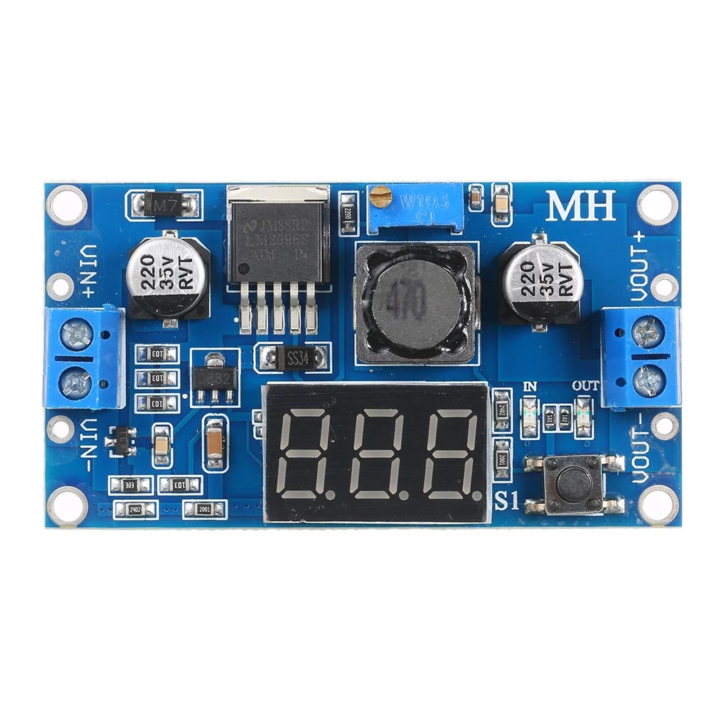
A stepdown converter, also known as a buck converter, is an electronic component designed to reduce a higher input voltage to a lower output voltage. The Stepdown 24V to 5V converter is specifically engineered to take an input voltage of 24 volts and step it down to a stable 5 volts. This component is widely used in applications where devices or circuits require a 5V power supply, such as microcontrollers, sensors, and USB-powered devices.
Explore Projects Built with stepdown 24v to 5v


Explore Projects Built with stepdown 24v to 5v
Common Applications and Use Cases
- Powering microcontrollers like Arduino, Raspberry Pi, or ESP32 from a 24V source.
- Supplying 5V to USB-powered devices in industrial or automotive environments.
- Converting 24V from solar panels or batteries to 5V for low-power electronics.
- Providing a stable 5V output for sensors, relays, and communication modules.
Technical Specifications
Below are the key technical details of the Stepdown 24V to 5V converter:
| Parameter | Value |
|---|---|
| Input Voltage Range | 6V to 24V |
| Output Voltage | 5V ± 0.1V |
| Maximum Output Current | 3A (with proper heat dissipation) |
| Efficiency | Up to 95% |
| Switching Frequency | 150 kHz |
| Operating Temperature | -40°C to +85°C |
| Dimensions | 25mm x 20mm x 10mm |
Pin Configuration and Descriptions
The Stepdown 24V to 5V converter typically has four pins or terminals:
| Pin/Terminal | Label | Description |
|---|---|---|
| 1 | VIN | Input voltage (6V to 24V). Connect to the 24V source. |
| 2 | GND | Ground connection for the input voltage. |
| 3 | VOUT | Regulated 5V output. Connect to the load/device. |
| 4 | GND | Ground connection for the output voltage. |
Usage Instructions
How to Use the Component in a Circuit
Connect the Input Voltage:
- Attach the VIN pin to the positive terminal of your 24V power source.
- Connect the GND pin to the ground terminal of your power source.
Connect the Output Voltage:
- Attach the VOUT pin to the positive terminal of the device or circuit requiring 5V.
- Connect the GND pin to the ground terminal of the device or circuit.
Verify Connections:
- Double-check all connections to ensure proper polarity and avoid short circuits.
Power On:
- Turn on the 24V power source. The converter will step down the voltage to 5V and supply it to the connected load.
Important Considerations and Best Practices
- Heat Dissipation: If the load draws a high current (close to 3A), ensure proper heat dissipation by attaching a heatsink or providing adequate ventilation.
- Input Voltage Range: Do not exceed the maximum input voltage of 24V, as this may damage the converter.
- Output Current Limit: Avoid exceeding the maximum output current of 3A to prevent overheating or failure.
- Filtering Capacitors: For improved stability, consider adding input and output capacitors (e.g., 100µF electrolytic capacitors) close to the converter.
Example: Using with an Arduino UNO
The Stepdown 24V to 5V converter can be used to power an Arduino UNO from a 24V source. Below is an example circuit and code:
Circuit Connections
- Connect the VIN pin of the converter to the 24V power source.
- Connect the GND pin of the converter to the ground of the power source.
- Connect the VOUT pin of the converter to the 5V pin of the Arduino UNO.
- Connect the GND pin of the converter to the GND pin of the Arduino UNO.
Arduino Code Example
// Example code to blink an LED connected to pin 13 of the Arduino UNO
// Ensure the Arduino is powered via the Stepdown 24V to 5V converter

void setup() {
  pinMode(13, OUTPUT); // Set pin 13 as an output
}

void loop() {
  digitalWrite(13, HIGH); // Turn the LED on
  delay(1000);            // Wait for 1 second
  digitalWrite(13, LOW);  // Turn the LED off
  delay(1000);            // Wait for 1 second
}
Troubleshooting and FAQs
Common Issues and Solutions
No Output Voltage:
- Cause: Incorrect wiring or loose connections.
- Solution: Verify all connections, ensuring proper polarity and secure contacts.
Overheating:
- Cause: Excessive current draw or insufficient heat dissipation.
- Solution: Reduce the load current or attach a heatsink to the converter.
Output Voltage Fluctuations:
- Cause: Insufficient input or output filtering.
- Solution: Add capacitors (e.g., 100µF electrolytic) to the input and output terminals.
Device Not Powering On:
- Cause: Output voltage is not reaching the device.
- Solution: Check the output voltage with a multimeter and ensure proper connections.
FAQs
Q1: Can I use this converter with a 12V input?
Yes, the converter supports input voltages as low as 6V, so it can step down 12V to 5V.
Q2: What happens if I exceed the 3A current limit?
Exceeding the current limit may cause the converter to overheat or shut down. Use a load that stays within the rated current.
Q3: Can I use this converter to charge a 5V USB device?
Yes, the converter can be used to charge USB devices, provided the current draw does not exceed 3A.
Q4: Is the output voltage adjustable?
No, this specific converter provides a fixed 5V output. For adjustable output, consider a different model.
Q5: Can I use this converter in automotive applications?
Yes, it can be used in automotive systems with a 24V battery, but ensure proper protection against voltage spikes.