How to Use 3.7V To 12V Mini DC Boost Converter Board Output 5V/8V/9V/12V DC Step Up Module Lith-Battery: Examples, Pinouts, and Specs
Documentation for Mini DC Boost Converter (3.7V to 12V)
1. Introduction
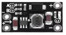
The Mini DC Boost Converter is a compact and efficient DC-DC step-up module designed to convert a low input voltage (3.7V) to a higher output voltage (up to 12V). This module is ideal for powering devices that require a stable higher voltage from a single lithium-ion battery or other low-voltage DC sources. With adjustable output voltages of 5V, 8V, 9V, and 12V, it is versatile and suitable for a wide range of applications.
Common Applications:
- Powering microcontrollers (e.g., Arduino, ESP32) from lithium batteries.
- Driving small DC motors or fans.
- Portable electronics and DIY projects.
- Emergency power supplies.
- LED lighting systems.
2. Technical Specifications
The following table outlines the key technical details of the Mini DC Boost Converter:
| Parameter | Specification |
|---|---|
| Input Voltage Range | 2.5V to 5.5V DC |
| Output Voltage Options | 5V, 8V, 9V, 12V DC (selectable via onboard switch) |
| Maximum Output Current | 1A (depending on input voltage and load conditions) |
| Efficiency | Up to 92% (varies with input/output voltage and load) |
| Dimensions | 30mm x 17mm x 14mm |
| Weight | ~5g |
| Operating Temperature | -40°C to +85°C |
Pin Configuration and Descriptions
| Pin Name | Description |
|---|---|
VIN |
Positive input voltage (connect to the positive terminal of the power source). |
GND |
Ground (connect to the negative terminal of the power source). |
VOUT |
Positive output voltage (connect to the load). |
GND |
Ground (common ground for input and output). |
3. Usage Instructions
Connecting the Mini DC Boost Converter:
- Input Connection: Connect the
VINpin to the positive terminal of your power source (e.g., a 3.7V lithium battery). Connect theGNDpin to the negative terminal of the power source. - Output Connection: Connect the
VOUTpin to the positive terminal of your load (e.g., an Arduino board, LED, or motor). Connect theGNDpin to the negative terminal of your load. - Voltage Selection: Use the onboard switch to select the desired output voltage (5V, 8V, 9V, or 12V). Ensure the selected voltage matches the requirements of your load.
Important Considerations:
- Input Voltage: Ensure the input voltage is within the specified range (2.5V to 5.5V). Exceeding this range may damage the module.
- Output Current: The maximum output current depends on the input voltage and load. Avoid exceeding 1A to prevent overheating or damage.
- Heat Dissipation: For high loads, ensure proper ventilation or add a heatsink to prevent overheating.
- Polarity: Double-check the polarity of your connections. Reversing the input or output connections may damage the module.
4. Example Application with Arduino UNO
The Mini DC Boost Converter can be used to power an Arduino UNO from a 3.7V lithium battery. Below is an example setup and code to blink an LED using the Arduino UNO powered by the boost converter.
Circuit Diagram:
- Connect the
VINpin of the boost converter to the positive terminal of the 3.7V lithium battery. - Connect the
GNDpin of the boost converter to the negative terminal of the battery. - Set the output voltage of the boost converter to 5V using the onboard switch.
- Connect the
VOUTpin of the boost converter to the5Vpin of the Arduino UNO. - Connect the
GNDpin of the boost converter to theGNDpin of the Arduino UNO. - Connect an LED to pin 13 of the Arduino UNO with a 220-ohm resistor in series.
Arduino Code:
// Blink an LED connected to pin 13 of the Arduino UNO
// Ensure the boost converter is set to output 5V to power the Arduino

void setup() {
  pinMode(13, OUTPUT); // Set pin 13 as an output pin
}

void loop() {
  digitalWrite(13, HIGH); // Turn the LED on
  delay(1000);            // Wait for 1 second
  digitalWrite(13, LOW);  // Turn the LED off
  delay(1000);            // Wait for 1 second
}
5. Troubleshooting and FAQs
Common Issues and Solutions:
| Issue | Possible Cause | Solution |
|---|---|---|
| No output voltage | Incorrect input connections or insufficient input voltage. | Verify input connections and ensure input voltage is within the range (2.5V-5.5V). |
| Output voltage is unstable or fluctuating. | Load exceeds the maximum current rating. | Reduce the load or ensure the load current is within the 1A limit. |
| Module overheats during operation. | High load current or poor ventilation. | Reduce the load or improve ventilation. Consider adding a heatsink. |
| Arduino does not power on. | Incorrect output voltage setting. | Ensure the output voltage is set to 5V for Arduino UNO. |
Frequently Asked Questions (FAQs):
Can I use this module to power a Raspberry Pi?
- Yes, but ensure the output voltage is set to 5V and the input source can provide sufficient current.
What happens if I reverse the input polarity?
- The module does not have reverse polarity protection. Reversing the input polarity may permanently damage the module.
Can I use this module with a solar panel?
- Yes, as long as the solar panel's output voltage is within the input range (2.5V to 5.5V) and provides sufficient current.
Is the output voltage adjustable beyond the preset values?
- No, the output voltage is fixed to the preset values (5V, 8V, 9V, 12V) and cannot be adjusted beyond these options.
6. Conclusion
The Mini DC Boost Converter is a versatile and compact solution for stepping up low DC voltages to higher levels, making it ideal for powering a variety of devices and projects. By following the usage instructions and best practices outlined in this documentation, users can maximize the performance and lifespan of the module. Whether you're working on a DIY project or a professional application, this boost converter is a reliable choice for efficient power conversion.
Explore Projects Built with 3.7V To 12V Mini DC Boost Converter Board Output 5V/8V/9V/12V DC Step Up Module Lith-Battery


Explore Projects Built with 3.7V To 12V Mini DC Boost Converter Board Output 5V/8V/9V/12V DC Step Up Module Lith-Battery