How to Use Buzzer Active: Examples, Pinouts, and Specs
Introduction
A Buzzer Active is an electronic component that produces sound when an electrical signal is applied. Unlike a passive buzzer, an active buzzer has an internal oscillator, meaning it can generate sound without requiring an external signal generator. It is commonly used in alarms, notifications, timers, and various signaling applications in consumer electronics, industrial devices, and embedded systems.
Explore Projects Built with Buzzer Active
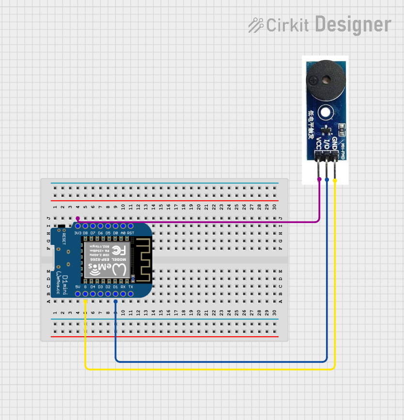
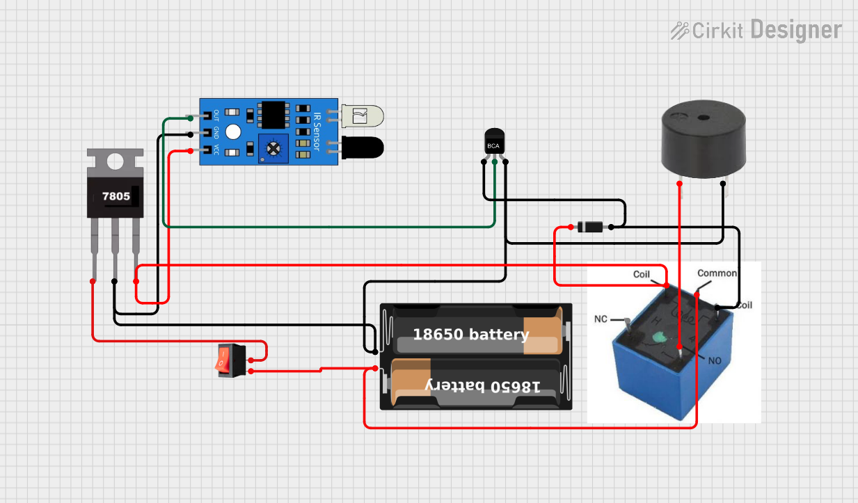
Explore Projects Built with Buzzer Active
Technical Specifications
- Operating Voltage: Typically 3V to 12V DC (check specific model for exact range)
- Operating Current: ~10mA to 30mA
- Sound Frequency: ~2kHz to 4kHz (varies by model)
- Sound Pressure Level (SPL): ~85dB to 100dB at 10cm
- Polarity: Active buzzers are polarized (positive and negative terminals must be connected correctly)
- Dimensions: Varies by model, typically cylindrical with a diameter of 5mm to 12mm
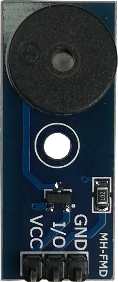
Pin Configuration and Descriptions
| Pin Name | Description |
|---|---|
| Positive (+) | Connect to the positive terminal of the power supply or microcontroller pin |
| Negative (-) | Connect to the ground (GND) of the circuit |
Usage Instructions
How to Use the Component in a Circuit
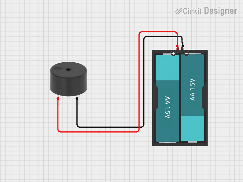
- Power Supply: Connect the positive pin of the buzzer to a DC voltage source (e.g., 5V) and the negative pin to ground. Ensure the voltage is within the operating range of the buzzer.
- Microcontroller Control: To control the buzzer with a microcontroller (e.g., Arduino UNO), connect the positive pin to a digital output pin and the negative pin to ground. Use the microcontroller to toggle the output pin HIGH or LOW to turn the buzzer on or off.
- Polarity: Ensure correct polarity when connecting the buzzer. Reversing the polarity may damage the component.
Important Considerations and Best Practices
- Voltage Range: Always operate the buzzer within its specified voltage range to avoid damage.
- Current Limiting: If the buzzer draws more current than the microcontroller pin can supply, use a transistor or MOSFET as a switch.
- Noise: Active buzzers can be loud. Consider using a resistor in series to reduce the sound level if needed.
- Placement: Place the buzzer away from sensitive components to avoid interference caused by vibrations.
Example: Connecting to an Arduino UNO
Below is an example of how to connect and control an active buzzer using an Arduino UNO.
Circuit Diagram
- Connect the positive pin of the buzzer to Arduino digital pin 8.
- Connect the negative pin of the buzzer to the Arduino GND.
Arduino Code
// Example code to control an active buzzer with Arduino UNO

// Define the pin connected to the buzzer
const int buzzerPin = 8;

void setup() {
  // Set the buzzer pin as an output
  pinMode(buzzerPin, OUTPUT);
}

void loop() {
  // Turn the buzzer ON
  digitalWrite(buzzerPin, HIGH);
  delay(1000); // Keep the buzzer ON for 1 second

  // Turn the buzzer OFF
  digitalWrite(buzzerPin, LOW);
  delay(1000); // Keep the buzzer OFF for 1 second
}
Troubleshooting and FAQs
Common Issues
No Sound from the Buzzer
- Cause: Incorrect polarity connection.
- Solution: Verify that the positive pin is connected to the power source or microcontroller output, and the negative pin is connected to ground.
Buzzer is Too Quiet
- Cause: Insufficient voltage or current.
- Solution: Ensure the power supply meets the buzzer's voltage and current requirements.
Buzzer Does Not Turn Off
- Cause: Microcontroller pin is stuck HIGH or there is a short circuit.
- Solution: Check the microcontroller code and wiring for errors.
Buzzer is Overheating
- Cause: Operating at a voltage higher than the specified range.
- Solution: Use a regulated power supply within the buzzer's operating voltage range.
FAQs
Q: Can I use an active buzzer with a 3.3V microcontroller?
A: Yes, as long as the buzzer's operating voltage includes 3.3V. Check the datasheet for compatibility.Q: How is an active buzzer different from a passive buzzer?
A: An active buzzer has an internal oscillator and can produce sound with a constant DC signal. A passive buzzer requires an external signal (e.g., PWM) to generate sound.Q: Can I adjust the sound frequency of an active buzzer?
A: No, the sound frequency of an active buzzer is fixed by its internal oscillator.Q: Is it safe to connect the buzzer directly to a microcontroller pin?
A: Yes, if the buzzer's current draw is within the microcontroller pin's output current limit. Otherwise, use a transistor or MOSFET as a switch.