
How to Use Triple Axis Accelerometer Breakout - ADXL335: Examples, Pinouts, and Specs
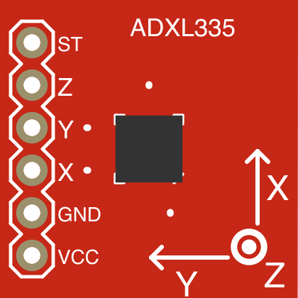
 Design with Triple Axis Accelerometer Breakout - ADXL335 in Cirkit Designer
Introduction
The Triple Axis Accelerometer Breakout - ADXL335 (Manufacturer Part ID: SEN-09269) is a compact sensor designed by SparkFun Electronics. It measures acceleration in three axes (X, Y, Z), enabling motion detection and orientation sensing. This analog-output accelerometer is ideal for applications requiring precise tilt, motion, or vibration measurements.
Explore Projects Built with Triple Axis Accelerometer Breakout - ADXL335
 Open Project in Cirkit Designer
 Open Project in Cirkit Designer
 Open Project in Cirkit Designer
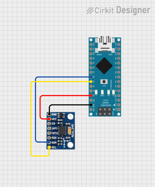 Open Project in Cirkit Designer
Explore Projects Built with Triple Axis Accelerometer Breakout - ADXL335
Open Project in Cirkit DesignerOpen Project in Cirkit DesignerOpen Project in Cirkit DesignerOpen Project in Cirkit DesignerCommon Applications
- Tilt sensing in robotics and drones
- Motion tracking in wearable devices
- Vibration monitoring in industrial equipment
- Gaming and virtual reality controllers
- Automotive impact detection systems
Technical Specifications
The ADXL335 is a low-power, small, and lightweight accelerometer with the following key specifications:
| Parameter | Value |
|---|---|
| Supply Voltage (Vcc) | 1.8V to 3.6V (typically 3.3V) |
| Output Voltage Range | 0V to Vcc |
| Measurement Range | ±3g |
| Sensitivity | 300 mV/g (at 3.3V supply) |
| Bandwidth (X, Y, Z axes) | 0.5 Hz to 1600 Hz (adjustable) |
| Operating Temperature | -40°C to +85°C |
| Dimensions | 20.3mm x 20.3mm |
| Weight | 1.5g |
Pin Configuration and Descriptions
The breakout board has a total of 5 pins. Below is the pinout and description:
| Pin | Name | Description |
|---|---|---|
| 1 | VCC | Power supply input (1.8V to 3.6V, typically 3.3V). |
| 2 | GND | Ground connection. |
| 3 | XOUT | Analog output voltage proportional to acceleration along the X-axis. |
| 4 | YOUT | Analog output voltage proportional to acceleration along the Y-axis. |
| 5 | ZOUT | Analog output voltage proportional to acceleration along the Z-axis. |
Usage Instructions
How to Use the ADXL335 in a Circuit
- Power the Sensor: Connect the
VCCpin to a 3.3V power source and theGNDpin to ground. - Connect the Outputs: Connect the
XOUT,YOUT, andZOUTpins to the analog input pins of a microcontroller (e.g., Arduino UNO). - Read the Outputs: The output voltages from the
XOUT,YOUT, andZOUTpins correspond to the acceleration along the respective axes. These voltages can be read using the ADC (Analog-to-Digital Converter) of the microcontroller. - Filter the Signal: Use external capacitors to set the bandwidth of the accelerometer. For example, a 0.1 µF capacitor on each axis sets the bandwidth to approximately 50 Hz.
Important Considerations and Best Practices
- Power Supply: Ensure a stable power supply to avoid noise in the output signals.
- Bandwidth Adjustment: Use appropriate capacitors to filter high-frequency noise and set the desired bandwidth.
- Orientation: Mount the sensor securely to avoid mechanical vibrations that could affect readings.
- Calibration: Perform calibration to account for sensor offsets and improve accuracy.
Example: Connecting to an Arduino UNO
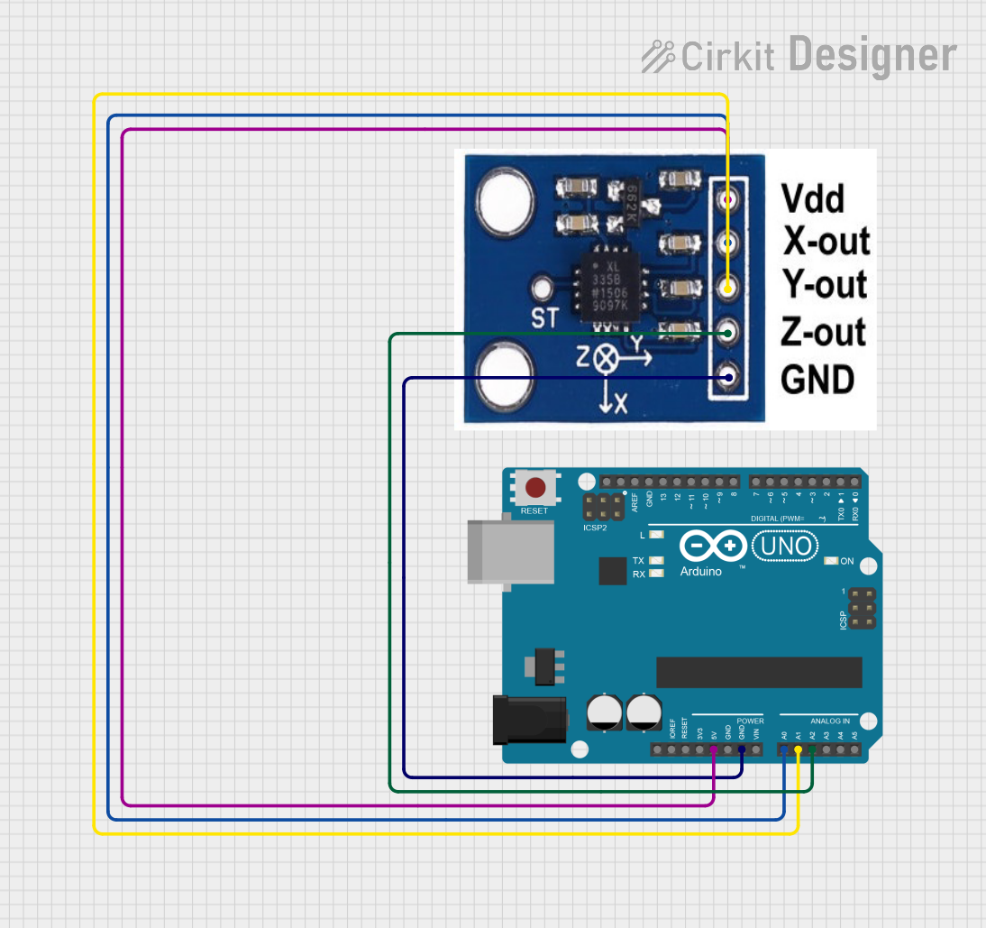
Below is an example of how to connect and read data from the ADXL335 using an Arduino UNO:
Circuit Connections
VCC→ 3.3V on ArduinoGND→ GND on ArduinoXOUT→ A0 on ArduinoYOUT→ A1 on ArduinoZOUT→ A2 on Arduino
Arduino Code
// Triple Axis Accelerometer Breakout - ADXL335 Example Code
// Reads acceleration data from the X, Y, and Z axes and prints it to the Serial Monitor.

const int xPin = A0; // X-axis output connected to analog pin A0
const int yPin = A1; // Y-axis output connected to analog pin A1
const int zPin = A2; // Z-axis output connected to analog pin A2

void setup() {
  Serial.begin(9600); // Initialize serial communication at 9600 baud
}

void loop() {
  // Read analog values from the accelerometer
  int xValue = analogRead(xPin);
  int yValue = analogRead(yPin);
  int zValue = analogRead(zPin);

  // Convert analog values to voltage (assuming 3.3V reference)
  float xVoltage = xValue * (3.3 / 1023.0);
  float yVoltage = yValue * (3.3 / 1023.0);
  float zVoltage = zValue * (3.3 / 1023.0);

  // Print the voltages to the Serial Monitor
  Serial.print("X Voltage: ");
  Serial.print(xVoltage);
  Serial.print(" V, Y Voltage: ");
  Serial.print(yVoltage);
  Serial.print(" V, Z Voltage: ");
  Serial.print(zVoltage);
  Serial.println(" V");

  delay(500); // Wait for 500ms before the next reading
}
Troubleshooting and FAQs
Common Issues
No Output Signal:
- Cause: Incorrect wiring or no power supply.
- Solution: Double-check all connections and ensure the sensor is powered.
Noisy Readings:
- Cause: High-frequency noise or unstable power supply.
- Solution: Add decoupling capacitors near the power pins and use appropriate bandwidth capacitors.
Incorrect Acceleration Values:
- Cause: Sensor not calibrated or mounted improperly.
- Solution: Perform calibration and ensure the sensor is securely mounted.
Output Voltage Exceeds Expected Range:
- Cause: Exceeding the sensor's ±3g range.
- Solution: Ensure the sensor is used within its specified range.
FAQs
Q1: Can the ADXL335 measure static acceleration (e.g., gravity)?
Yes, the ADXL335 can measure static acceleration, such as gravity, making it suitable for tilt sensing.
Q2: How do I calculate acceleration from the output voltage?
Acceleration (in g) = (Output Voltage - Zero-g Voltage) / Sensitivity.
For example, at 3.3V supply, the zero-g voltage is approximately 1.65V, and the sensitivity is 300 mV/g.
Q3: Can I use the ADXL335 with a 5V microcontroller?
Yes, but you must use a voltage divider or level shifter to ensure the sensor's output voltages are compatible with the microcontroller's ADC.
Q4: What is the maximum detectable acceleration?
The ADXL335 can measure accelerations up to ±3g.
By following this documentation, you can effectively integrate the ADXL335 into your projects for reliable motion and orientation sensing.