Cirkit Designer Logo
Cirkit Designer
Your all-in-one circuit design IDE
Home / 
Component Documentation

How to Use Power module pixhawk kecil: Examples, Pinouts, and Specs

Image of Power module pixhawk kecil
Cirkit Designer LogoDesign with Power module pixhawk kecil in Cirkit Designer

Introduction

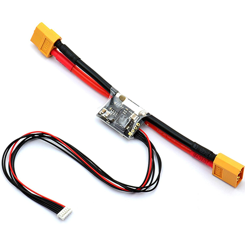
The Power Module Pixhawk Kecil is a compact and efficient power module designed specifically for Pixhawk flight controllers. It provides regulated power and current sensing capabilities, making it an essential component for drones and other Unmanned Aerial Vehicles (UAVs). This module ensures that your flight controller receives a stable power supply while also monitoring the current consumption, which is crucial for maintaining the health and performance of your UAV.

Explore Projects Built with Power module pixhawk kecil

Use Cirkit Designer to design, explore, and prototype these projects online. Some projects support real-time simulation. Click "Open Project" to start designing instantly!
Battery-Powered Pixhawk Power Module with Rocker Switch Control
Image of power: A project utilizing Power module pixhawk kecil in a practical application
This circuit is designed to power a Pixhawk module using a LiPo battery. The circuit includes a rocker switch to control the power flow from the battery to a power distribution board (PDB), which then supplies 12V to the Pixhawk module.
Cirkit Designer LogoOpen Project in Cirkit Designer
Raspberry Pi-Controlled Drone with Brushless Motors and Camera Module
Image of ROV: A project utilizing Power module pixhawk kecil in a practical application
This circuit is designed for a multi-motor application, likely a drone or a similar vehicle, featuring eight brushless motors controlled by two 4-in-1 electronic speed controllers (ESCs). The ESCs are powered by a 3s2p 18650 battery pack and interfaced with a Pixhawk flight controller for motor management. Additionally, the system includes a Raspberry Pi 4B for advanced processing and control, which is connected to a NoIR camera module and a cooling fan, and a power module to supply and monitor the power to the Pixhawk.
Cirkit Designer LogoOpen Project in Cirkit Designer
Battery-Powered FPV Drone with Telemetry and Dual Motor Control
Image of Krul': A project utilizing Power module pixhawk kecil in a practical application
This circuit appears to be a power distribution and control system for a vehicle with two motorized wheels, possibly a drone or a robot. It includes a lipo battery connected to a Power Distribution Board (PDB) that distributes power to two Electronic Speed Controllers (ESCs) which in turn control the speed and direction of the motors. The system also integrates a flight controller (H743-SLIM V3) for managing various peripherals including GPS, FPV camera system, and a telemetry link (ExpressLRS).
Cirkit Designer LogoOpen Project in Cirkit Designer
Battery-Powered Quadcopter with BLDC Motors and GPS
Image of file: A project utilizing Power module pixhawk kecil in a practical application
This circuit is designed for a quadcopter, featuring four BLDC motors each controlled by an Electronic Speed Controller (ESC). The ESCs are powered by a LiPo battery through a power module, and the system is managed by an APM 2.0 flight controller, which also interfaces with a GPS module, an RC receiver, and telemetry for communication.
Cirkit Designer LogoOpen Project in Cirkit Designer

Explore Projects Built with Power module pixhawk kecil

Use Cirkit Designer to design, explore, and prototype these projects online. Some projects support real-time simulation. Click "Open Project" to start designing instantly!
Image of power: A project utilizing Power module pixhawk kecil in a practical application
Battery-Powered Pixhawk Power Module with Rocker Switch Control
This circuit is designed to power a Pixhawk module using a LiPo battery. The circuit includes a rocker switch to control the power flow from the battery to a power distribution board (PDB), which then supplies 12V to the Pixhawk module.
Cirkit Designer LogoOpen Project in Cirkit Designer
Image of ROV: A project utilizing Power module pixhawk kecil in a practical application
Raspberry Pi-Controlled Drone with Brushless Motors and Camera Module
This circuit is designed for a multi-motor application, likely a drone or a similar vehicle, featuring eight brushless motors controlled by two 4-in-1 electronic speed controllers (ESCs). The ESCs are powered by a 3s2p 18650 battery pack and interfaced with a Pixhawk flight controller for motor management. Additionally, the system includes a Raspberry Pi 4B for advanced processing and control, which is connected to a NoIR camera module and a cooling fan, and a power module to supply and monitor the power to the Pixhawk.
Cirkit Designer LogoOpen Project in Cirkit Designer
Image of Krul': A project utilizing Power module pixhawk kecil in a practical application
Battery-Powered FPV Drone with Telemetry and Dual Motor Control
This circuit appears to be a power distribution and control system for a vehicle with two motorized wheels, possibly a drone or a robot. It includes a lipo battery connected to a Power Distribution Board (PDB) that distributes power to two Electronic Speed Controllers (ESCs) which in turn control the speed and direction of the motors. The system also integrates a flight controller (H743-SLIM V3) for managing various peripherals including GPS, FPV camera system, and a telemetry link (ExpressLRS).
Cirkit Designer LogoOpen Project in Cirkit Designer
Image of file: A project utilizing Power module pixhawk kecil in a practical application
Battery-Powered Quadcopter with BLDC Motors and GPS
This circuit is designed for a quadcopter, featuring four BLDC motors each controlled by an Electronic Speed Controller (ESC). The ESCs are powered by a LiPo battery through a power module, and the system is managed by an APM 2.0 flight controller, which also interfaces with a GPS module, an RC receiver, and telemetry for communication.
Cirkit Designer LogoOpen Project in Cirkit Designer

Common Applications and Use Cases

  • Drones and UAVs: Provides stable power and current monitoring for flight controllers.
  • Robotics: Supplies regulated power to robotic systems and monitors current usage.
  • RC Vehicles: Ensures reliable power delivery and current sensing for remote-controlled vehicles.
  • DIY Electronics Projects: Ideal for any project requiring regulated power and current monitoring.

Technical Specifications

Key Technical Details

Parameter Value
Input Voltage 4.5V - 28V
Output Voltage 5.3V ± 0.1V
Max Current Output 3A
Current Sensing 0 - 90A
Connector Type XT60 for input and output
Weight 25 grams
Dimensions 25mm x 21mm x 9mm

Pin Configuration and Descriptions

Pin Number Pin Name Description
1 VCC Regulated 5.3V output to Pixhawk
2 GND Ground
3 Current Analog current sensor output
4 Voltage Analog voltage sensor output
5 VCC (Input) Unregulated input voltage (4.5V - 28V)
6 GND (Input) Ground

Usage Instructions

How to Use the Component in a Circuit

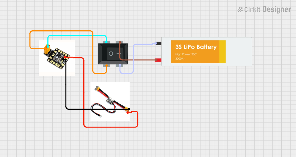
  1. Connect the Input Power:

    • Connect the input power source (battery) to the XT60 connector labeled as input.
    • Ensure the input voltage is within the range of 4.5V to 28V.
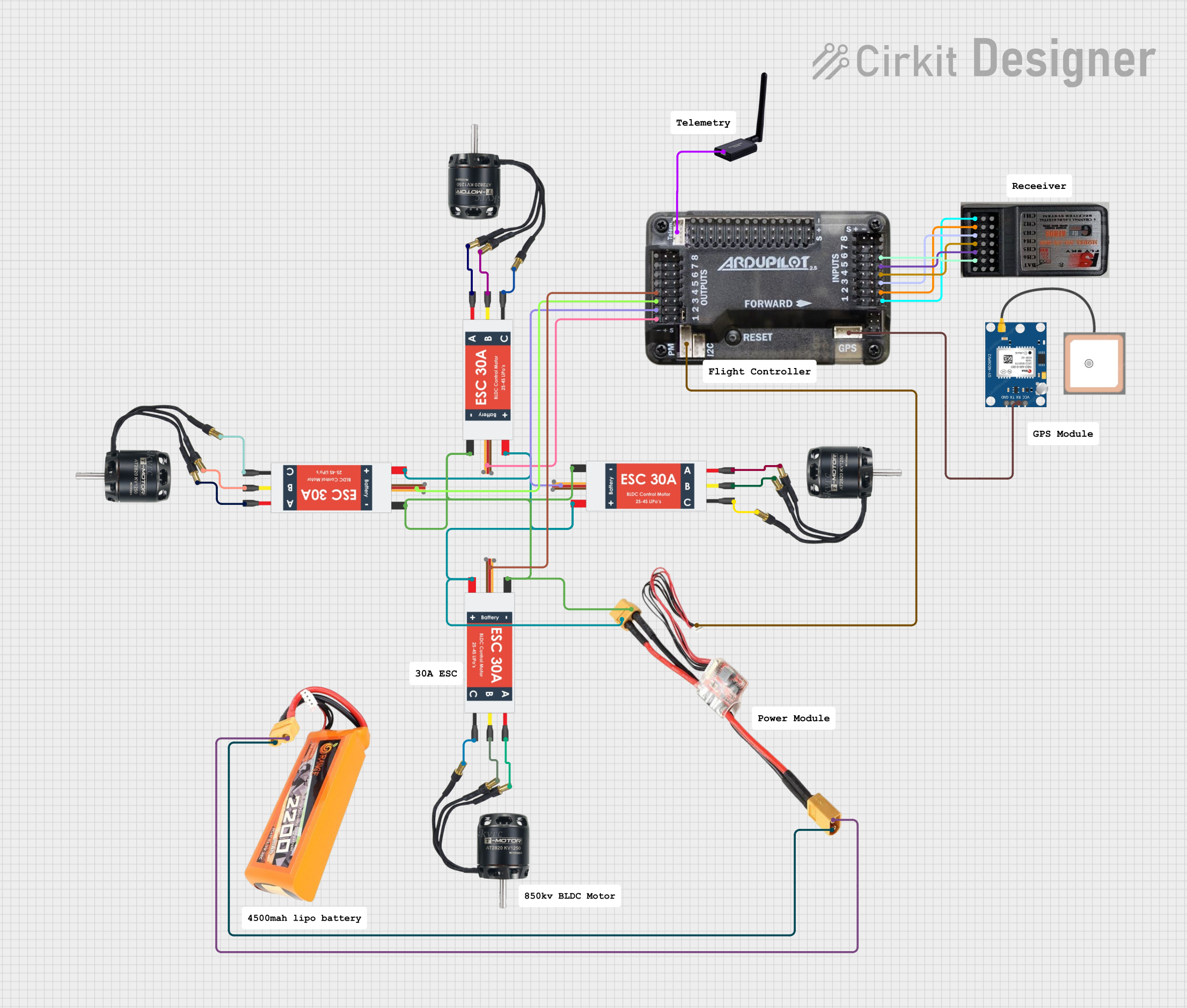
  2. Connect to Pixhawk:

    • Use the provided cable to connect the VCC, GND, Current, and Voltage pins to the corresponding pins on the Pixhawk flight controller.
    • Ensure the connections are secure and correct to avoid damage.
  3. Monitor Current and Voltage:

    • The Current and Voltage pins provide analog signals that can be read by the Pixhawk for monitoring purposes.
    • Configure the Pixhawk software to read these values for real-time monitoring.

Important Considerations and Best Practices

  • Voltage Range: Ensure the input voltage does not exceed 28V to prevent damage to the module.
  • Current Rating: Do not exceed the maximum current output of 3A to maintain safe operation.
  • Secure Connections: Ensure all connections are secure to prevent intermittent power loss.
  • Heat Dissipation: Although the module is efficient, ensure adequate ventilation to prevent overheating.

Troubleshooting and FAQs

Common Issues Users Might Face

  1. No Power Output:

    • Solution: Check the input voltage and ensure it is within the specified range. Verify all connections are secure.
  2. Inaccurate Current Sensing:

    • Solution: Calibrate the current sensor in the Pixhawk software to ensure accurate readings.
  3. Overheating:

    • Solution: Ensure the module is not enclosed in a tight space and has adequate ventilation.
  4. Intermittent Power Loss:

    • Solution: Check all connections for any loose wires or connectors. Ensure the input power source is stable.

FAQs

Q1: Can I use this power module with other flight controllers?

  • A1: Yes, as long as the flight controller supports the input voltage and current sensing capabilities.

Q2: How do I calibrate the current sensor in Pixhawk?

  • A2: Refer to the Pixhawk documentation for detailed instructions on calibrating the current sensor.

Q3: What is the maximum current this module can handle?

  • A3: The module can handle a maximum current output of 3A.

Q4: Can I use this module for non-UAV applications?

  • A4: Yes, this module can be used in any application requiring regulated power and current sensing.

Example Code for Arduino UNO

If you are using this power module with an Arduino UNO for current and voltage monitoring, you can use the following example code:

// Define the analog pins for current and voltage sensing
const int currentPin = A0;
const int voltagePin = A1;

void setup() {
  // Initialize serial communication
  Serial.begin(9600);
}

void loop() {
  // Read the analog values from the current and voltage pins
  int currentValue = analogRead(currentPin);
  int voltageValue = analogRead(voltagePin);

  // Convert the analog values to actual current and voltage
  float current = (currentValue / 1023.0) * 90.0; // Assuming 0-90A range
  float voltage = (voltageValue / 1023.0) * 28.0; // Assuming 0-28V range

  // Print the current and voltage values to the serial monitor
  Serial.print("Current: ");
  Serial.print(current);
  Serial.print(" A, Voltage: ");
  Serial.print(voltage);
  Serial.println(" V");

  // Wait for a second before the next reading
  delay(1000);
}

This code reads the analog values from the current and voltage pins, converts them to actual current and voltage values, and prints them to the serial monitor. Adjust the conversion formulas based on your specific requirements.


This documentation provides a comprehensive guide to using the Power Module Pixhawk Kecil, ensuring both beginners and experienced users can effectively integrate it into their projects.