How to Use LCD Display 20x4 : Examples, Pinouts, and Specs
Introduction
The 16x4 LCD (Liquid Crystal Display) is an electronic display module capable of displaying 16 characters per line across 4 lines. It is widely used in various devices for displaying alphanumeric information such as sensor data, time, menus, and status messages.
Explore Projects Built with LCD Display 20x4


Explore Projects Built with LCD Display 20x4
Common Applications and Use Cases
- User interfaces for electronic devices
- Real-time data output displays
- DIY projects with microcontrollers (e.g., Arduino)
- Information panels in appliances and machines
Technical Specifications
Key Technical Details
- Display Mode: STN or FSTN
- Display Type: 16 characters x 4 lines
- Character Size: Typically 5x8 or 5x11 dots
- Module Dimension: Varies with model (check datasheet)
- Viewing Area: Varies with model (check datasheet)
- Operating Voltage: Typically 4.5V to 5.5V
- Supply Current: 1mA (typical) without backlight, 20mA (with backlight)
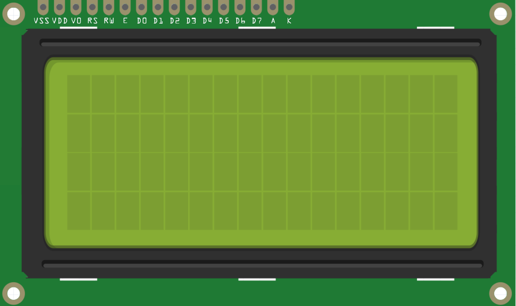
Pin Configuration and Descriptions
| Pin Number | Symbol | Function |
|---|---|---|
| 1 | VSS | Ground |
| 2 | VDD | Supply Voltage for Logic |
| 3 | VO | Contrast Adjustment |
| 4 | RS | Register Select: 0 for Instruction, 1 for Data |
| 5 | R/W | Read/Write: 0 for Write, 1 for Read |
| 6 | E | Enable Signal |
| 7-14 | D0-D7 | Data Bus Line |
| 15 | LED+ | Backlight Anode (+) |
| 16 | LED- | Backlight Cathode (-) |
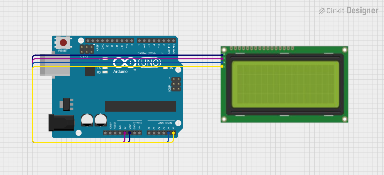
Usage Instructions
How to Use the Component in a Circuit
- Power Connections: Connect pin 1 (VSS) to ground and pin 2 (VDD) to a 5V supply.
- Contrast Adjustment: Connect pin 3 (VO) to a variable resistor (potentiometer) to adjust the display contrast.
- Data Interface: Connect pins 7-14 (D0-D7) to the microcontroller data pins for 8-bit mode or use only D4-D7 for 4-bit mode.
- Control Pins: Connect RS and R/W to microcontroller I/O pins. Set RS to select command/data register and R/W to read/write.
- Enable Pin: Connect the E pin to a microcontroller I/O pin. Pulse this pin high to process data/command.
- Backlight: Connect pin 15 (LED+) to 5V through a current-limiting resistor and pin 16 (LED-) to ground.
Important Considerations and Best Practices
- Always consult the datasheet for exact pin configuration and specifications.
- Use a current-limiting resistor for the backlight to prevent damage.
- Avoid static discharge by grounding yourself before handling the LCD.
- Ensure that the power supply is stable and within the specified voltage range.
Example Code for Arduino UNO
#include <LiquidCrystal.h>

// Initialize the library with the interface pins
LiquidCrystal lcd(12, 11, 5, 4, 3, 2);

void setup() {
  // Set up the LCD's number of columns and rows:
  lcd.begin(16, 4);
  // Print a message to the LCD.
  lcd.print("Hello, World!");
}

void loop() {
  // Set the cursor to column 0, line 1
  lcd.setCursor(0, 1);
  // Print the number of seconds since reset:
  lcd.print(millis() / 1000);
}
Troubleshooting and FAQs
Common Issues Users Might Face
- Display is blank or characters are not visible: Adjust the contrast potentiometer.
- Garbled or incorrect characters: Check data connections and ensure proper initialization in code.
- Backlight not working: Verify the connection of the backlight pins and the current-limiting resistor.
Solutions and Tips for Troubleshooting
- Double-check wiring against the pin configuration.
- Ensure that the Arduino library used matches the LCD model.
- Reset the power to the LCD module if it behaves unexpectedly.
FAQs
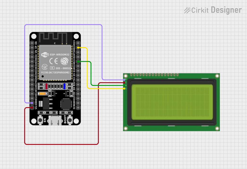
Q: Can I use the LCD with a 3.3V system? A: It depends on the specific LCD model. Check the datasheet; some models are compatible with 3.3V logic.
Q: How can I display custom characters?
A: The LCD controller allows you to create custom characters. Refer to the createChar() function in the Arduino LiquidCrystal library.
Q: What is the lifespan of the LCD? A: LCDs typically have a long lifespan, often 50,000 hours or more, but this can be affected by operating conditions and backlight usage.
Q: Can I use the LCD in extreme temperatures? A: Operating temperature ranges vary by model. Check the datasheet for temperature limits to ensure proper operation.