
How to Use Adafruit Feather 32u4 FONA: Examples, Pinouts, and Specs
 Design with Adafruit Feather 32u4 FONA in Cirkit Designer
Introduction
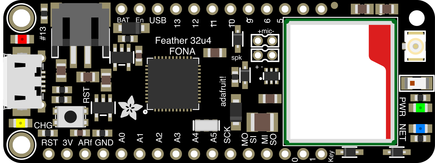
The Adafruit Feather 32u4 FONA (Manufacturer Part ID: 3027) is a compact and versatile microcontroller board designed for IoT (Internet of Things) applications. It features an ATmega32u4 processor, built-in GSM (Global System for Mobile Communications) and GPS (Global Positioning System) capabilities, and USB connectivity. This board is ideal for projects requiring cellular communication, location tracking, or remote data logging. Its small form factor and compatibility with various sensors and modules make it a popular choice for developers and hobbyists alike.
Explore Projects Built with Adafruit Feather 32u4 FONA
 Open Project in Cirkit Designer
 Open Project in Cirkit Designer
 Open Project in Cirkit Designer
 Open Project in Cirkit Designer
Explore Projects Built with Adafruit Feather 32u4 FONA
Open Project in Cirkit DesignerOpen Project in Cirkit DesignerOpen Project in Cirkit DesignerOpen Project in Cirkit DesignerCommon Applications
- IoT devices with GSM connectivity
- GPS-based location tracking systems
- Remote data logging and telemetry
- SMS-based control systems
- Prototyping cellular-enabled projects
Technical Specifications
Key Technical Details
| Specification | Value |
|---|---|
| Microcontroller | ATmega32u4 |
| Operating Voltage | 3.3V |
| Input Voltage (USB or LiPo) | 3.7V to 6V |
| Clock Speed | 8 MHz |
| Flash Memory | 32 KB (2.75 KB used by bootloader) |
| SRAM | 2.5 KB |
| EEPROM | 1 KB |
| GSM Module | SIM800H |
| GPS Capability | Assisted GPS (via GSM module) |
| USB Interface | Micro USB |
| Battery Support | 3.7V LiPo battery (with charging circuit) |
| Dimensions | 51mm x 23mm x 8mm |
| Weight | 8.2g |
Pin Configuration and Descriptions
| Pin Name | Description |
|---|---|
| GND | Ground pin |
| 3V | 3.3V output pin |
| BAT | LiPo battery input pin |
| USB | USB power input pin |
| TX | UART Transmit pin (connected to SIM800H) |
| RX | UART Receive pin (connected to SIM800H) |
| D0-D13 | Digital I/O pins |
| A0-A5 | Analog input pins |
| SDA | I2C data pin |
| SCL | I2C clock pin |
| RST | Reset pin |
| EN | Enable pin (used to enable/disable the board) |
| CHG | Battery charging status indicator pin |
| KEY | Power key for GSM module (used to turn the module on/off) |
Usage Instructions
How to Use the Component in a Circuit
Powering the Board:
- Connect a 3.7V LiPo battery to the BAT pin or power the board via the Micro USB port.
- Ensure the input voltage does not exceed 6V to avoid damaging the board.
Connecting to GSM Network:
- Insert a micro SIM card into the SIM800H module's SIM card slot.
- Use the
KEYpin to turn on the GSM module (pull the pin low for 2 seconds).
Interfacing with Sensors:
- Use the digital (D0-D13) and analog (A0-A5) pins to connect sensors or actuators.
- For I2C devices, connect to the SDA and SCL pins.
Programming the Board:
- Connect the board to your computer via the Micro USB port.
- Use the Arduino IDE to upload code. Select "Adafruit Feather 32u4" as the board type.
Using GPS:
- The GPS functionality is integrated into the SIM800H module. Use AT commands to retrieve GPS data.
Important Considerations and Best Practices
- Always use a proper antenna for GSM and GPS functionality to ensure reliable performance.
- Avoid powering the board solely through the USB port when using GSM features, as the module may require higher current during operation.
- Use level shifters if interfacing with 5V logic devices, as the board operates at 3.3V logic levels.
- Ensure the SIM card is activated and has sufficient balance for GSM operations.
Example Code for Arduino UNO
Below is an example code snippet to send an SMS using the Adafruit Feather 32u4 FONA:
#include <Adafruit_FONA.h>

// Define FONA serial connection
#define FONA_RX 9  // RX pin connected to Feather TX
#define FONA_TX 8  // TX pin connected to Feather RX
#define FONA_RST 4 // Reset pin for FONA module

// Create FONA object
Adafruit_FONA fona = Adafruit_FONA(FONA_RST);

void setup() {
  // Initialize serial communication
  Serial.begin(115200);
  Serial.println(F("Initializing FONA..."));

  // Initialize FONA module
  if (!fona.begin(Serial1)) {
    Serial.println(F("Couldn't find FONA module!"));
    while (1);
  }
  Serial.println(F("FONA is ready!"));

  // Set SMS mode to text
  fona.setSMSInterrupt(1);
  fona.sendSMS("+1234567890", "Hello from Adafruit Feather 32u4 FONA!");
  Serial.println(F("SMS sent!"));
}

void loop() {
  // Add your main code here
}
Notes:
- Replace
+1234567890with the recipient's phone number. - Ensure the GSM module is powered on and connected to a network before running the code.
Troubleshooting and FAQs
Common Issues and Solutions
Board Not Detected by Computer:
- Ensure the USB cable is functional and supports data transfer.
- Check if the correct board type is selected in the Arduino IDE.
GSM Module Not Connecting to Network:
- Verify that the SIM card is properly inserted and activated.
- Check the antenna connection and ensure good signal strength.
GPS Data Not Available:
- Ensure the GSM module is powered on and has a clear view of the sky.
- Wait for a few minutes for the GPS to acquire satellite signals.
Battery Not Charging:
- Verify the LiPo battery connection and ensure the input voltage is within range.
- Check the CHG pin for charging status.
FAQs
Q: Can I use the board without a battery?
A: Yes, the board can be powered via the Micro USB port, but a battery is recommended for GSM operations due to higher current requirements.
Q: What is the maximum current draw of the GSM module?
A: The SIM800H module can draw up to 2A during transmission bursts. Ensure your power source can handle this.
Q: Can I use this board with 5V sensors?
A: The board operates at 3.3V logic levels. Use level shifters to interface with 5V sensors.
Q: How do I update the firmware on the GSM module?
A: Firmware updates can be performed via the UART interface. Refer to the SIM800H datasheet for detailed instructions.