
How to Use PMS7003 : Examples, Pinouts, and Specs
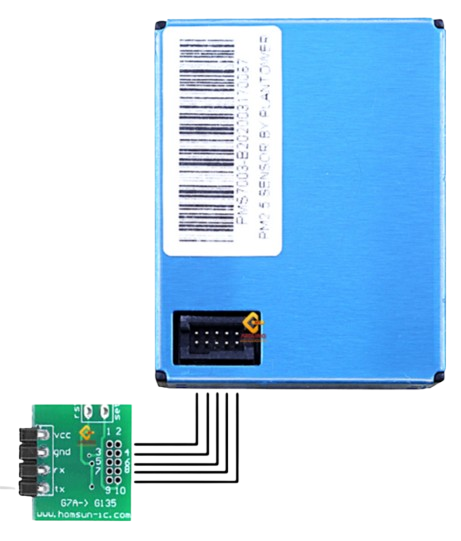
 Design with PMS7003 in Cirkit Designer
Introduction
The PMS7003 is a laser-based particulate matter sensor designed to measure concentrations of PM1.0, PM2.5, and PM10 particles in the air. It utilizes laser scattering technology to provide highly accurate and real-time air quality data. The sensor is compact, reliable, and easy to integrate into various systems, making it ideal for environmental monitoring, indoor air quality assessment, and air purifier applications.
Explore Projects Built with PMS7003
 Open Project in Cirkit Designer
 Open Project in Cirkit Designer
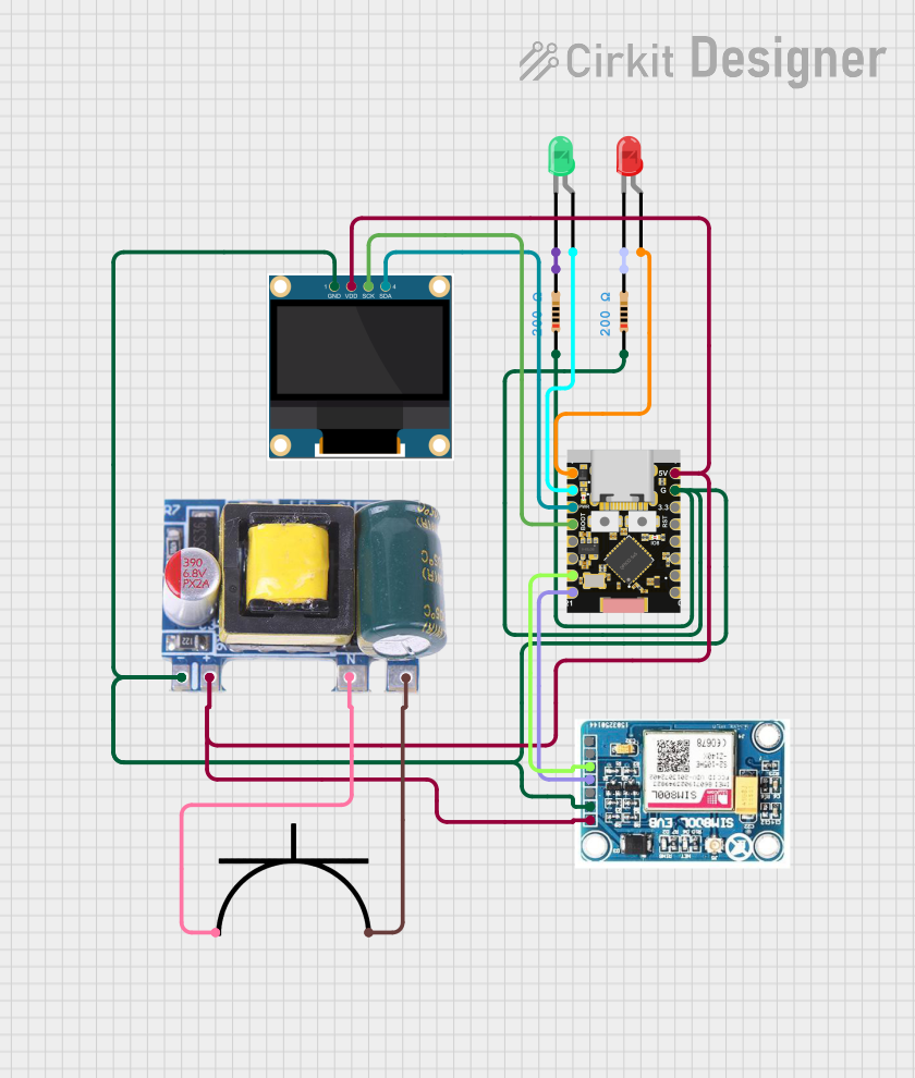 Open Project in Cirkit Designer
 Open Project in Cirkit Designer
Explore Projects Built with PMS7003
Open Project in Cirkit DesignerOpen Project in Cirkit DesignerOpen Project in Cirkit DesignerOpen Project in Cirkit DesignerCommon Applications
- Air quality monitoring stations
- Smart home devices and air purifiers
- HVAC systems
- IoT-based environmental monitoring
- Industrial air quality control
Technical Specifications
Key Technical Details
| Parameter | Value |
|---|---|
| Operating Voltage | 4.5V to 5.5V |
| Operating Current | ≤ 100mA |
| Standby Current | ≤ 200µA |
| Particle Size Detection | 0.3µm to 10µm |
| Measurement Range | 0 to 1,000 µg/m³ |
| Response Time | ≤ 1 second |
| Data Output | UART (9600 bps, 8N1) |
| Operating Temperature | -10°C to +60°C |
| Operating Humidity | 0% to 99% RH (non-condensing) |
| Dimensions | 50mm x 38mm x 21mm |
Pin Configuration and Descriptions
| Pin Number | Pin Name | Description |
|---|---|---|
| 1 | VCC | Power supply input (4.5V to 5.5V) |
| 2 | GND | Ground connection |
| 3 | SET | Standby mode control (active low) |
| 4 | RXD | UART receive pin (connect to MCU TX) |
| 5 | TXD | UART transmit pin (connect to MCU RX) |
| 6 | RESET | Reset pin (active low) |
Usage Instructions
How to Use the PMS7003 in a Circuit
- Power Supply: Connect the VCC pin to a 5V power source and the GND pin to ground.
- UART Communication: Connect the TXD pin of the PMS7003 to the RX pin of your microcontroller (e.g., Arduino UNO) and the RXD pin of the PMS7003 to the TX pin of the microcontroller.
- Standby Mode: Use the SET pin to control standby mode. Pull it low to enter standby mode and high to resume normal operation.
- Reset: Optionally, connect the RESET pin to a GPIO pin on your microcontroller for manual resets.
Important Considerations
- Airflow: Ensure proper airflow through the sensor for accurate readings. Avoid obstructing the air inlet and outlet.
- Orientation: Install the sensor in the recommended orientation (horizontal) for optimal performance.
- Power Stability: Use a stable power supply to avoid fluctuations that could affect sensor accuracy.
- Warm-Up Time: Allow the sensor to warm up for 30 seconds after powering on for stable readings.
Example Code for Arduino UNO
Below is an example Arduino sketch to interface with the PMS7003 and read particulate matter data:
#include <SoftwareSerial.h>

// Define RX and TX pins for SoftwareSerial
SoftwareSerial pms7003Serial(10, 11); // RX = pin 10, TX = pin 11

// Buffer to store incoming data from the sensor
uint8_t pmsData[32];

void setup() {
  Serial.begin(9600); // Initialize Serial Monitor
  pms7003Serial.begin(9600); // Initialize PMS7003 UART communication

  Serial.println("PMS7003 Sensor Initialized");
}

void loop() {
  if (pms7003Serial.available() >= 32) {
    // Read 32 bytes of data from the sensor
    for (int i = 0; i < 32; i++) {
      pmsData[i] = pms7003Serial.read();
    }

    // Validate the data frame
    if (pmsData[0] == 0x42 && pmsData[1] == 0x4D) {
      // Extract PM2.5 concentration (bytes 12 and 13)
      uint16_t pm25 = (pmsData[12] << 8) | pmsData[13];

      // Extract PM10 concentration (bytes 14 and 15)
      uint16_t pm10 = (pmsData[14] << 8) | pmsData[15];

      // Print the results to the Serial Monitor
      Serial.print("PM2.5: ");
      Serial.print(pm25);
      Serial.print(" µg/m³, PM10: ");
      Serial.print(pm10);
      Serial.println(" µg/m³");
    }
  }

  delay(1000); // Wait 1 second before reading again
}
Notes on the Code
- The
SoftwareSeriallibrary is used to create a secondary UART interface for the PMS7003. - Ensure the RX and TX pins are correctly connected to the PMS7003.
- The code reads and validates the 32-byte data frame from the sensor and extracts PM2.5 and PM10 concentrations.
Troubleshooting and FAQs
Common Issues and Solutions
No Data Output:
- Ensure the sensor is powered correctly (4.5V to 5.5V).
- Verify the UART connections (TXD to RX, RXD to TX).
- Check the baud rate (9600 bps) in your code.
Inaccurate Readings:
- Ensure proper airflow through the sensor.
- Avoid placing the sensor in high humidity or dusty environments without protection.
- Allow the sensor to warm up for at least 30 seconds after powering on.
Sensor Not Responding:
- Check the SET pin. Ensure it is pulled high for normal operation.
- Verify the RESET pin is not being held low.
FAQs
Q: Can the PMS7003 detect particles smaller than 0.3µm?
A: No, the PMS7003 is designed to detect particles in the range of 0.3µm to 10µm.
Q: How often should I calibrate the sensor?
A: The PMS7003 is factory-calibrated and does not require frequent calibration. However, periodic validation against a reference instrument is recommended for critical applications.
Q: Can I use the PMS7003 outdoors?
A: The PMS7003 is not weatherproof. If used outdoors, it must be housed in a protective enclosure with proper airflow.
Q: What is the lifespan of the PMS7003?
A: The sensor has an estimated lifespan of 3 years under normal operating conditions.