How to Use BT136 TRAIC DRIMMER MODULE: Examples, Pinouts, and Specs
Introduction
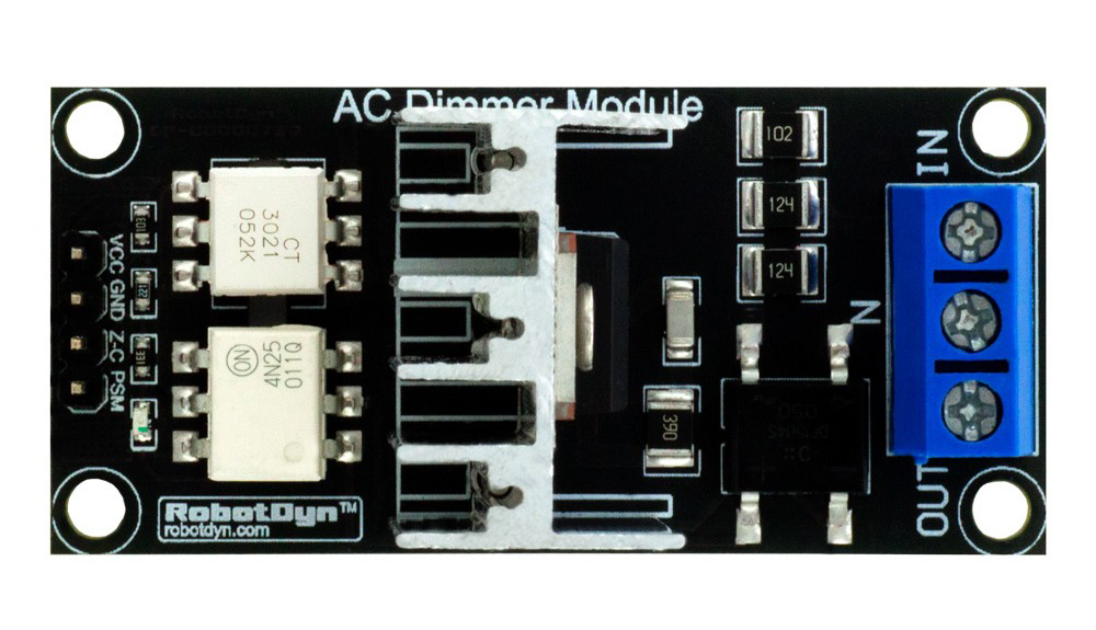
The BT136 TRIAC Dimmer Module is an electronic component designed for controlling the power delivered to AC loads. It is based on the BT136 TRIAC, a robust and reliable semiconductor device manufactured by WeEn Semiconductors and NXP. This module is widely used in applications requiring dimming, speed control, or power regulation for AC devices such as lights, fans, and heaters.
Explore Projects Built with BT136 TRAIC DRIMMER MODULE
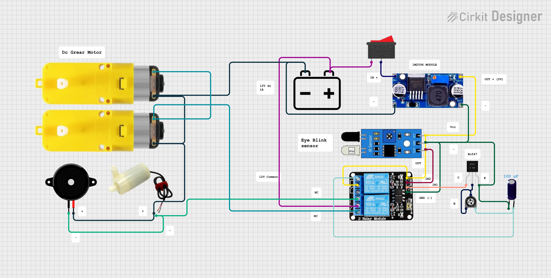


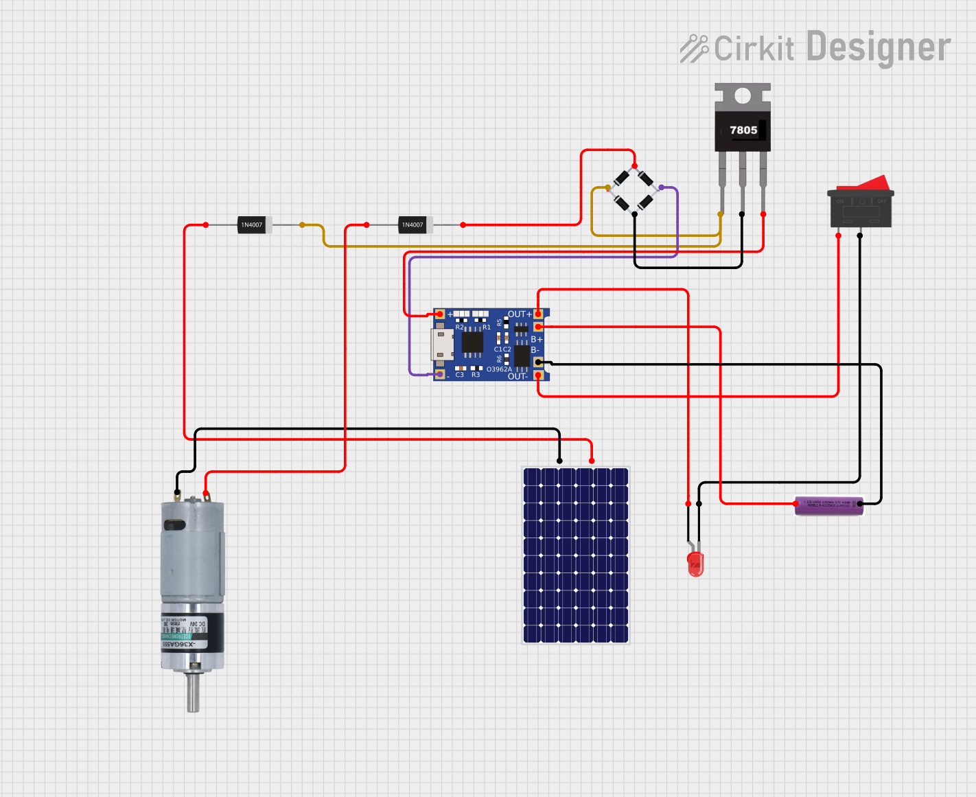
Explore Projects Built with BT136 TRAIC DRIMMER MODULE
Common Applications and Use Cases
- Light dimming for incandescent and LED bulbs (with compatible drivers)
- Speed control for AC motors (e.g., fans, drills)
- Temperature control in heating systems
- General-purpose AC power regulation in home automation systems
Technical Specifications
Key Technical Details
- Manufacturer Part ID: BT136 (WeEn Semiconductors and NXP)
- Voltage Rating: 600V (maximum repetitive peak off-state voltage)
- Current Rating: 4A (RMS on-state current)
- Trigger Voltage: 0.7V to 1.5V (gate threshold voltage)
- Power Dissipation: 2W (typical)
- Operating Temperature: -40°C to +125°C
- Isolation Voltage: 1500V (between terminals and heatsink)
Pin Configuration and Descriptions
The BT136 TRIAC Dimmer Module typically has three main terminals and an additional input for control. Below is the pin configuration:
| Pin Name | Description |
|---|---|
| MT1 | Main Terminal 1: Connected to one side of the AC load. |
| MT2 | Main Terminal 2: Connected to the other side of the AC load and AC power line. |
| Gate | Gate Terminal: Used to trigger the TRIAC into conduction. |
| Control Input | Input signal for controlling the dimmer module (e.g., from a microcontroller). |
Usage Instructions
How to Use the Component in a Circuit
- Power Connections: Connect the AC load in series with the MT1 and MT2 terminals of the module. Ensure the load is within the current and voltage ratings of the BT136 TRIAC.
- Control Signal: Provide a control signal to the Gate terminal via the Control Input. This signal can be generated using a microcontroller, such as an Arduino, or a manual potentiometer circuit.
- Triggering the TRIAC: The TRIAC is triggered into conduction when a sufficient voltage is applied to the Gate terminal. Once triggered, it remains in conduction until the AC current crosses zero.
Important Considerations and Best Practices
- Heat Dissipation: Ensure proper heat sinking for the module, especially when operating near its maximum current rating.
- Snubber Circuit: Use a snubber circuit (resistor and capacitor in series) across MT1 and MT2 to suppress voltage spikes and prevent false triggering.
- Isolation: If controlling the module with a microcontroller, use an optocoupler to isolate the low-voltage control circuit from the high-voltage AC circuit.
- Load Compatibility: Verify that the load is compatible with TRIAC-based dimming. Some LED drivers and electronic ballasts may not work properly.
Example: Using the BT136 TRIAC Dimmer Module with Arduino UNO
Below is an example of how to control the BT136 TRIAC Dimmer Module using an Arduino UNO:
/*
  Example: Controlling BT136 TRIAC Dimmer Module with Arduino UNO
  This code demonstrates how to dim an AC light using PWM control.
  Note: Ensure proper isolation and safety precautions when working with AC power.
*/

#define TRIAC_PIN 9  // Pin connected to the Gate terminal of the TRIAC module

void setup() {
  pinMode(TRIAC_PIN, OUTPUT);  // Set TRIAC_PIN as an output
}

void loop() {
  for (int brightness = 0; brightness <= 255; brightness += 5) {
    // Gradually increase brightness
    analogWrite(TRIAC_PIN, brightness);
    delay(50);  // Wait 50ms
  }

  for (int brightness = 255; brightness >= 0; brightness -= 5) {
    // Gradually decrease brightness
    analogWrite(TRIAC_PIN, brightness);
    delay(50);  // Wait 50ms
  }
}
Note: The above code assumes the use of a zero-crossing detection circuit to synchronize the TRIAC triggering with the AC waveform. Without zero-crossing detection, the dimming may not work as expected.
Troubleshooting and FAQs
Common Issues and Solutions
The load does not turn on:
- Ensure the Gate terminal is receiving a sufficient trigger voltage.
- Verify that the load is properly connected to MT1 and MT2.
- Check for a blown fuse or tripped circuit breaker in the AC line.
Flickering or unstable dimming:
- Add a snubber circuit across MT1 and MT2 to suppress voltage spikes.
- Ensure the control signal is synchronized with the AC zero-crossing point.
Overheating of the module:
- Check that the load current does not exceed the TRIAC's maximum rating.
- Use an appropriate heatsink to dissipate heat effectively.
Microcontroller resets when controlling the TRIAC:
- Use an optocoupler to isolate the microcontroller from the high-voltage AC circuit.
- Ensure proper grounding and shielding of the control circuit.
FAQs
Can the BT136 TRIAC Dimmer Module be used with DC loads? No, the BT136 TRIAC is designed for AC loads only. It cannot regulate DC power.
What types of loads are compatible with the module? The module works well with resistive loads (e.g., incandescent bulbs, heaters) and some inductive loads (e.g., fans, motors). Compatibility with LED drivers depends on the driver design.
Is it safe to use the module without a heatsink? For low-power applications, a heatsink may not be necessary. However, for higher currents, a heatsink is essential to prevent overheating.
Do I need a zero-crossing detection circuit? Yes, for precise dimming control, a zero-crossing detection circuit is recommended to synchronize the TRIAC triggering with the AC waveform.