Cirkit Designer Logo
Cirkit Designer
Your all-in-one circuit design IDE
Home / 
Component Documentation

How to Use ZS-x11H: Examples, Pinouts, and Specs

Image of ZS-x11H
Cirkit Designer LogoDesign with ZS-x11H in Cirkit Designer

Introduction

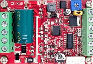
The ZS-x11H is a high-performance, low-power microcontroller designed for embedded systems. It features multiple I/O ports, integrated memory, and advanced power management capabilities, making it suitable for a wide range of applications. This microcontroller is ideal for use in consumer electronics, industrial automation, IoT devices, and more.

Explore Projects Built with ZS-x11H

Use Cirkit Designer to design, explore, and prototype these projects online. Some projects support real-time simulation. Click "Open Project" to start designing instantly!
Satellite-Based Timing and Navigation System with SDR and Atomic Clock Synchronization
Image of GPS 시스템 측정 구성도_Confirm: A project utilizing ZS-x11H in a practical application
This circuit appears to be a complex system involving power supply management, GPS and timing synchronization, and data communication. It includes a SI-TEX G1 Satellite Compass for GPS data, an XHTF1021 Atomic Rubidium Clock for precise timing, and Ettus USRP B200 units for software-defined radio communication. Power is supplied through various SMPS units and distributed via terminal blocks and DC jacks. Data communication is facilitated by Beelink MINI S12 N95 computers, RS232 splitters, and a 1000BASE-T Media Converter for network connectivity. RF Directional Couplers are used to interface antennas with the USRP units, and the entire system is likely contained within cases for protection and organization.
Cirkit Designer LogoOpen Project in Cirkit Designer
ESP32 Smart Socket with Energy Monitoring and OLED Display
Image of Energy Meter: A project utilizing ZS-x11H in a practical application
This circuit is a smart socket for energy monitoring, utilizing an ESP32 microcontroller to read voltage and current from ZMPT101B and ACS712 sensors. The readings are displayed on a 0.96" OLED screen, and a relay module is used to control a connected load, such as a bulb, remotely. The system is powered by a 220V AC source, converted to DC by an HLK-PM01 module.
Cirkit Designer LogoOpen Project in Cirkit Designer
Arduino Nano-Based Remote-Controlled Dual Motor System with LiPo Battery
Image of nano shield zkbm1: A project utilizing ZS-x11H in a practical application
This circuit is designed to control two GM25 DC motors using a ZK-BM1 10A motor driver, which is managed by a NANO Shield Board. The NANO Shield Board receives input signals from an R6FG receiver and is powered by an 11.1V LiPo battery.
Cirkit Designer LogoOpen Project in Cirkit Designer
ESP32-Based Smart Energy Monitoring and Control System
Image of SMART SOCKET: A project utilizing ZS-x11H in a practical application
This circuit is designed to monitor AC voltage and current using ZMPT101B and ZMCT103C sensors, respectively, with an ESP32 microcontroller processing the sensor outputs. The XL4015 step-down module regulates the power supply to provide a stable voltage to the sensors, the ESP32, and an LCD I2C display. The ESP32 controls a 4-channel relay module for switching AC loads, and the system's operation can be interacted with via the LCD display and a push switch.
Cirkit Designer LogoOpen Project in Cirkit Designer

Explore Projects Built with ZS-x11H

Use Cirkit Designer to design, explore, and prototype these projects online. Some projects support real-time simulation. Click "Open Project" to start designing instantly!
Image of GPS 시스템 측정 구성도_Confirm: A project utilizing ZS-x11H in a practical application
Satellite-Based Timing and Navigation System with SDR and Atomic Clock Synchronization
This circuit appears to be a complex system involving power supply management, GPS and timing synchronization, and data communication. It includes a SI-TEX G1 Satellite Compass for GPS data, an XHTF1021 Atomic Rubidium Clock for precise timing, and Ettus USRP B200 units for software-defined radio communication. Power is supplied through various SMPS units and distributed via terminal blocks and DC jacks. Data communication is facilitated by Beelink MINI S12 N95 computers, RS232 splitters, and a 1000BASE-T Media Converter for network connectivity. RF Directional Couplers are used to interface antennas with the USRP units, and the entire system is likely contained within cases for protection and organization.
Cirkit Designer LogoOpen Project in Cirkit Designer
Image of Energy Meter: A project utilizing ZS-x11H in a practical application
ESP32 Smart Socket with Energy Monitoring and OLED Display
This circuit is a smart socket for energy monitoring, utilizing an ESP32 microcontroller to read voltage and current from ZMPT101B and ACS712 sensors. The readings are displayed on a 0.96" OLED screen, and a relay module is used to control a connected load, such as a bulb, remotely. The system is powered by a 220V AC source, converted to DC by an HLK-PM01 module.
Cirkit Designer LogoOpen Project in Cirkit Designer
Image of nano shield zkbm1: A project utilizing ZS-x11H in a practical application
Arduino Nano-Based Remote-Controlled Dual Motor System with LiPo Battery
This circuit is designed to control two GM25 DC motors using a ZK-BM1 10A motor driver, which is managed by a NANO Shield Board. The NANO Shield Board receives input signals from an R6FG receiver and is powered by an 11.1V LiPo battery.
Cirkit Designer LogoOpen Project in Cirkit Designer
Image of SMART SOCKET: A project utilizing ZS-x11H in a practical application
ESP32-Based Smart Energy Monitoring and Control System
This circuit is designed to monitor AC voltage and current using ZMPT101B and ZMCT103C sensors, respectively, with an ESP32 microcontroller processing the sensor outputs. The XL4015 step-down module regulates the power supply to provide a stable voltage to the sensors, the ESP32, and an LCD I2C display. The ESP32 controls a 4-channel relay module for switching AC loads, and the system's operation can be interacted with via the LCD display and a push switch.
Cirkit Designer LogoOpen Project in Cirkit Designer

Technical Specifications

Key Technical Details

Parameter Value
Operating Voltage 1.8V - 3.6V
Operating Temperature -40°C to 85°C
Flash Memory 64KB
SRAM 8KB
I/O Pins 32
ADC Channels 8
PWM Channels 4
Communication Interfaces UART, SPI, I2C
Power Consumption 0.5µA (sleep mode)

Pin Configuration and Descriptions

Pin Number Pin Name Description
1 VCC Power Supply (1.8V - 3.6V)
2 GND Ground
3 PA0 GPIO / ADC Channel 0
4 PA1 GPIO / ADC Channel 1
5 PA2 GPIO / ADC Channel 2
6 PA3 GPIO / ADC Channel 3
7 PA4 GPIO / ADC Channel 4
8 PA5 GPIO / ADC Channel 5
9 PA6 GPIO / ADC Channel 6
10 PA7 GPIO / ADC Channel 7
11 PB0 GPIO / PWM Channel 0
12 PB1 GPIO / PWM Channel 1
13 PB2 GPIO / PWM Channel 2
14 PB3 GPIO / PWM Channel 3
15 PC0 GPIO / UART TX
16 PC1 GPIO / UART RX
17 PC2 GPIO / SPI MOSI
18 PC3 GPIO / SPI MISO
19 PC4 GPIO / SPI SCK
20 PC5 GPIO / I2C SDA
21 PC6 GPIO / I2C SCL
22 PD0 GPIO
23 PD1 GPIO
24 PD2 GPIO
25 PD3 GPIO
26 PD4 GPIO
27 PD5 GPIO
28 PD6 GPIO
29 PD7 GPIO
30 RESET Reset
31 XTAL1 External Oscillator Input
32 XTAL2 External Oscillator Output

Usage Instructions

How to Use the ZS-x11H in a Circuit

  1. Power Supply: Connect the VCC pin to a power supply within the range of 1.8V to 3.6V and the GND pin to ground.
  2. I/O Configuration: Configure the I/O pins as needed for your application. The ZS-x11H supports multiple functions on each pin, such as GPIO, ADC, PWM, UART, SPI, and I2C.
  3. Programming: Use a compatible programmer to upload your firmware to the ZS-x11H. Ensure that the RESET pin is properly connected to the programmer.
  4. External Oscillator: If an external oscillator is required, connect it to the XTAL1 and XTAL2 pins.

Important Considerations and Best Practices

  • Power Management: Utilize the advanced power management features to reduce power consumption, especially in battery-powered applications.
  • Pin Multiplexing: Be mindful of the pin multiplexing options to avoid conflicts between different peripheral functions.
  • Decoupling Capacitors: Place decoupling capacitors close to the VCC pin to ensure stable power supply and reduce noise.
  • Firmware Updates: Regularly update the firmware to incorporate bug fixes and new features.

Example Code for Arduino UNO

The following example demonstrates how to interface the ZS-x11H with an Arduino UNO using the UART communication interface.

// Include the SoftwareSerial library for UART communication
#include <SoftwareSerial.h>

// Define the RX and TX pins for SoftwareSerial
#define RX_PIN 10
#define TX_PIN 11

// Create a SoftwareSerial object
SoftwareSerial zsSerial(RX_PIN, TX_PIN);

void setup() {
  // Initialize the hardware serial port for debugging
  Serial.begin(9600);
  
  // Initialize the software serial port for ZS-x11H communication
  zsSerial.begin(9600);
  
  // Print a message to the serial monitor
  Serial.println("ZS-x11H Communication Initialized");
}

void loop() {
  // Check if data is available from the ZS-x11H
  if (zsSerial.available()) {
    // Read the incoming data
    char incomingData = zsSerial.read();
    
    // Print the incoming data to the serial monitor
    Serial.print("Received: ");
    Serial.println(incomingData);
  }
  
  // Send a test message to the ZS-x11H
  zsSerial.println("Hello ZS-x11H");
  
  // Wait for a second before sending the next message
  delay(1000);
}

Troubleshooting and FAQs

Common Issues

  1. No Communication with ZS-x11H:

    • Solution: Ensure that the RX and TX pins are correctly connected. Verify the baud rate settings in the code.
  2. Microcontroller Not Powering On:

    • Solution: Check the power supply voltage and connections. Ensure that the VCC and GND pins are properly connected.
  3. Unexpected Behavior:

    • Solution: Verify the pin configurations and ensure there are no conflicts between peripheral functions. Check for firmware bugs and update if necessary.

FAQs

Q1: Can I use the ZS-x11H with a 5V power supply?

  • A1: No, the ZS-x11H operates within a voltage range of 1.8V to 3.6V. Using a 5V power supply may damage the microcontroller.

Q2: How do I update the firmware on the ZS-x11H?

  • A2: Use a compatible programmer to upload the new firmware. Ensure that the RESET pin is connected to the programmer during the update process.

Q3: Can I use multiple communication interfaces simultaneously?

  • A3: Yes, the ZS-x11H supports multiple communication interfaces (UART, SPI, I2C). However, ensure that there are no pin conflicts when configuring the interfaces.

This documentation provides a comprehensive guide to using the ZS-x11H microcontroller. Whether you are a beginner or an experienced user, following these instructions and best practices will help you effectively integrate the ZS-x11H into your projects.