How to Use Joystick: Examples, Pinouts, and Specs
Introduction
A joystick is an input device used to control video games or computer graphics. It consists of a stick that pivots on a base and reports its angle or direction to the device it is controlling. Joysticks are widely used in gaming, robotics, and other applications requiring precise directional control. They typically provide two-axis analog output (X and Y) and may include additional features such as a push-button for added functionality.
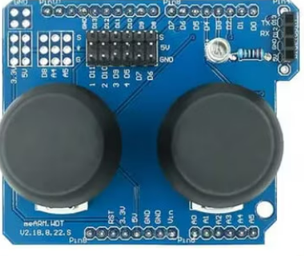
Explore Projects Built with Joystick


Explore Projects Built with Joystick
Common Applications and Use Cases
- Gaming controllers for PCs and consoles
- Robotic control systems
- Camera gimbals and pan-tilt mechanisms
- Remote-controlled vehicles and drones
- Industrial machinery control
Technical Specifications
Below are the general technical specifications for a standard analog joystick module:
| Parameter | Value |
|---|---|
| Operating Voltage | 3.3V - 5V |
| Output Type | Analog (X, Y axes) and Digital (button) |
| X-Axis Range | 0V to Vcc (centered at ~Vcc/2) |
| Y-Axis Range | 0V to Vcc (centered at ~Vcc/2) |
| Button Output | Digital (active LOW) |
| Dimensions | ~34mm x 34mm x 32mm |
Pin Configuration and Descriptions
The joystick module typically has 5 pins. The table below describes each pin:
| Pin | Name | Description |
|---|---|---|
| 1 | GND | Ground connection |
| 2 | VCC | Power supply (3.3V or 5V) |
| 3 | VRx | Analog output for the X-axis (horizontal movement) |
| 4 | VRy | Analog output for the Y-axis (vertical movement) |
| 5 | SW | Digital output for the push-button (active LOW when pressed, HIGH otherwise) |
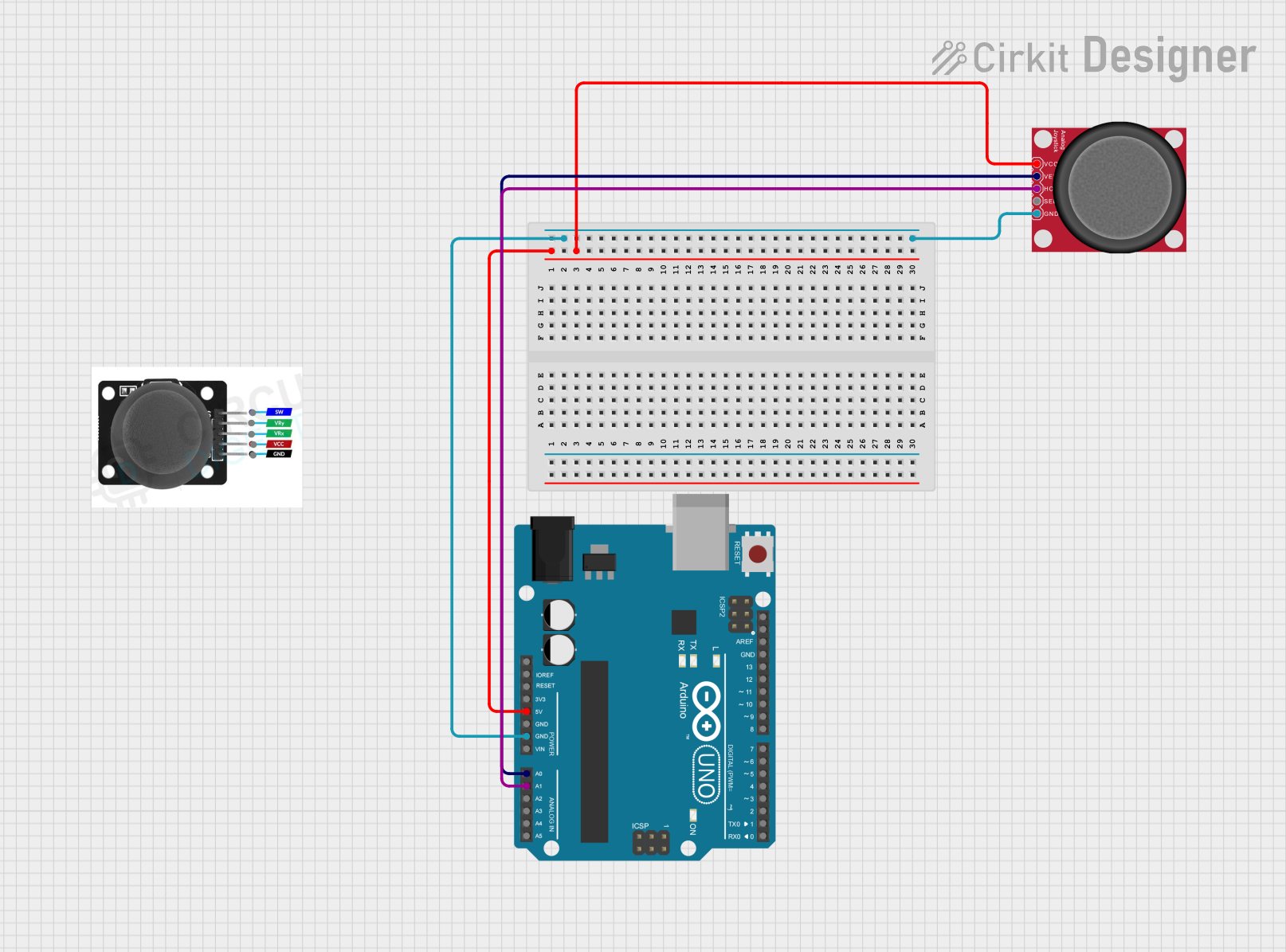
Usage Instructions
How to Use the Joystick in a Circuit
- Connect the Power Supply:
- Connect the
VCCpin to a 3.3V or 5V power source. - Connect the
GNDpin to the ground of your circuit.
- Connect the
- Connect the Analog Outputs:
- Connect the
VRxpin to an analog input pin on your microcontroller to read the X-axis position. - Connect the
VRypin to another analog input pin to read the Y-axis position.
- Connect the
- Connect the Button Output:
- Connect the
SWpin to a digital input pin on your microcontroller to detect button presses.
- Connect the
Important Considerations and Best Practices
- Voltage Compatibility: Ensure the joystick's operating voltage matches your microcontroller's input voltage (e.g., 5V for Arduino UNO).
- Debouncing the Button: If the button is used, consider implementing software debouncing to avoid false triggers.
- Center Calibration: The joystick's analog outputs are centered at approximately half the supply voltage when in the neutral position. Use this as a reference for calibration in your code.
- Mechanical Durability: Avoid applying excessive force to the joystick to prevent damage.
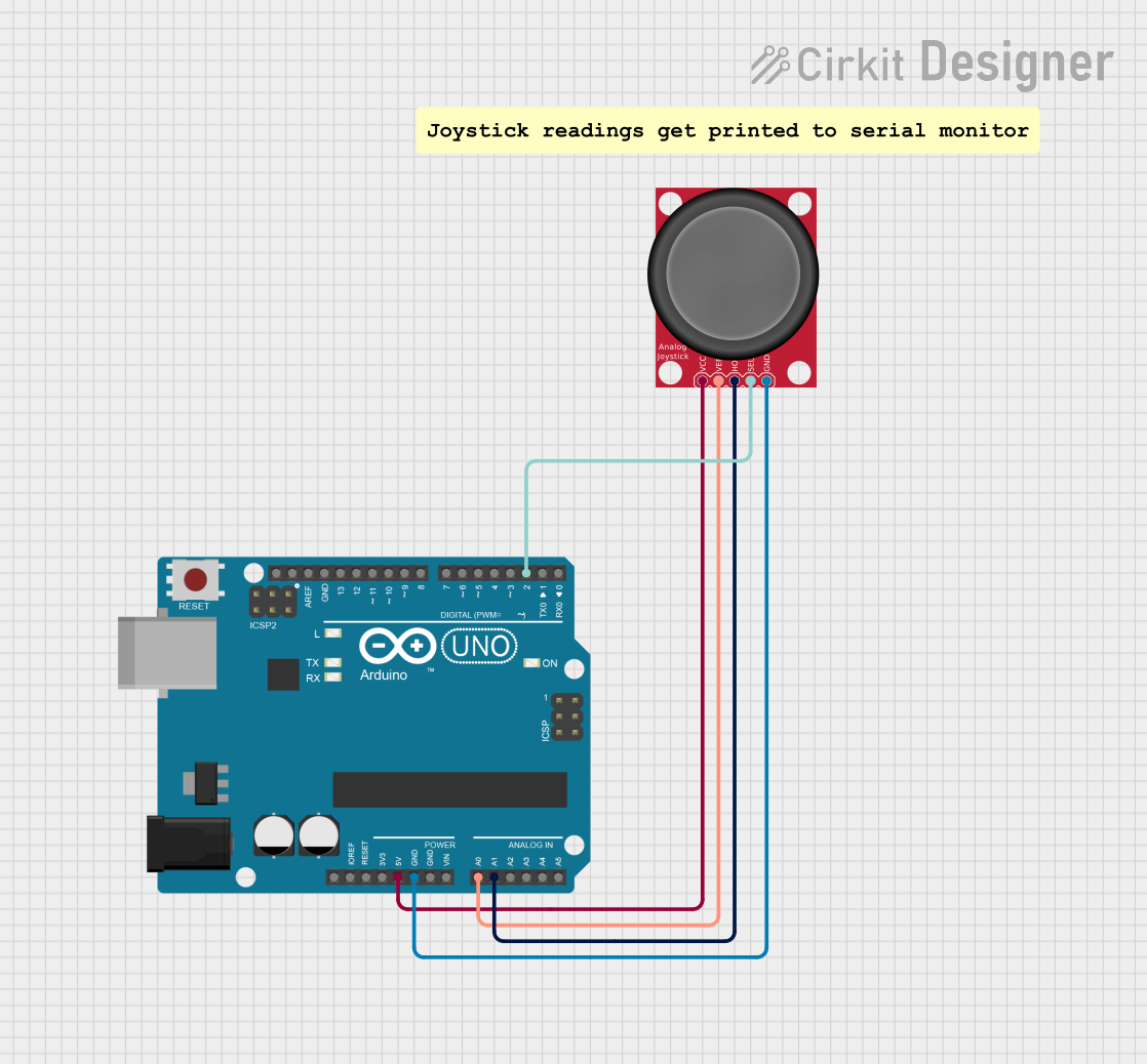
Example: Using the Joystick with Arduino UNO
Below is an example Arduino sketch to read the joystick's X, Y, and button states:
// Define pin connections
const int VRxPin = A0; // X-axis connected to analog pin A0
const int VRyPin = A1; // Y-axis connected to analog pin A1
const int SWPin = 2;   // Button connected to digital pin 2

void setup() {
  // Initialize serial communication for debugging
  Serial.begin(9600);

  // Configure the button pin as input with pull-up resistor
  pinMode(SWPin, INPUT_PULLUP);
}

void loop() {
  // Read the X and Y axis values (0 to 1023)
  int xValue = analogRead(VRxPin);
  int yValue = analogRead(VRyPin);

  // Read the button state (LOW when pressed, HIGH otherwise)
  int buttonState = digitalRead(SWPin);

  // Print the values to the Serial Monitor
  Serial.print("X: ");
  Serial.print(xValue);
  Serial.print(" | Y: ");
  Serial.print(yValue);
  Serial.print(" | Button: ");
  Serial.println(buttonState == LOW ? "Pressed" : "Released");

  // Add a small delay for stability
  delay(100);
}
Notes:
- The analog values for
VRxandVRywill range from 0 to 1023 on a 10-bit ADC (e.g., Arduino UNO). - The button state will be
LOWwhen pressed andHIGHwhen released due to the pull-up resistor.
Troubleshooting and FAQs
Common Issues and Solutions
Joystick Outputs Not Changing:
- Cause: Loose or incorrect wiring.
- Solution: Double-check all connections, especially the
VRxandVRypins.
Button Not Responding:
- Cause: Missing pull-up resistor or incorrect pin configuration.
- Solution: Use the
INPUT_PULLUPmode in your code or add an external pull-up resistor.
Inconsistent Analog Readings:
- Cause: Electrical noise or poor power supply.
- Solution: Add decoupling capacitors (e.g., 0.1µF) near the power pins to stabilize the voltage.
Joystick Center Not Calibrated:
- Cause: Manufacturing tolerances.
- Solution: Implement software calibration to adjust for the neutral position.
FAQs
Q: Can I use the joystick with a Raspberry Pi?
A: Yes, the joystick can be used with a Raspberry Pi. Connect the analog outputs to an ADC (e.g., MCP3008) since the Raspberry Pi lacks built-in analog input pins.
Q: What is the lifespan of a joystick module?
A: The lifespan depends on usage and build quality. Most modules are rated for thousands of cycles of operation.
Q: Can I use the joystick for 3D control?
A: Standard joysticks provide 2D control (X and Y axes). For 3D control, you would need a joystick with an additional Z-axis or a separate input device.
Q: How do I extend the joystick's cable length?
A: Use shielded cables to minimize noise and signal degradation over longer distances.