How to Use AD5933 Impedance Converter: Examples, Pinouts, and Specs
Introduction
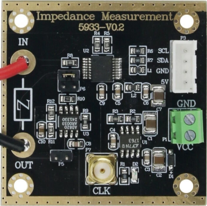
The AD5933 is a high-precision impedance converter manufactured by Generic, with the part ID AD5933. It is designed to measure the impedance of a device under test (DUT) across a wide frequency range. The device integrates a frequency generator, an analog-to-digital converter (ADC), and a digital signal processor (DSP) to provide accurate impedance measurements. By generating a sine wave and analyzing the resulting voltage and phase shift, the AD5933 calculates the impedance of the DUT.
Explore Projects Built with AD5933 Impedance Converter


Explore Projects Built with AD5933 Impedance Converter
Common Applications and Use Cases
- Bio-impedance measurements for medical devices
- Material characterization in research and development
- Corrosion monitoring in industrial systems
- Sensor interfacing for capacitive, inductive, or resistive sensors
- Quality control in manufacturing processes
Technical Specifications
Key Technical Details
- Operating Voltage: 2.7 V to 5.5 V
- Frequency Range: 1 kHz to 100 kHz (programmable)
- Impedance Measurement Range: 1 kΩ to 10 MΩ (with external components)
- Output Excitation Voltage: Programmable (200 mV, 400 mV, or 1 V peak-to-peak)
- ADC Resolution: 12-bit
- Interface: I²C (2-wire serial interface)
- Operating Temperature Range: -40°C to +125°C
- Package: 16-lead TSSOP
Pin Configuration and Descriptions
The AD5933 is housed in a 16-lead TSSOP package. Below is the pin configuration:
| Pin Number | Pin Name | Description |
|---|---|---|
| 1 | VDD | Positive power supply (2.7 V to 5.5 V). |
| 2 | AGND | Analog ground. |
| 3 | VOUT | Output of the programmable sine wave generator. |
| 4 | RFB | Feedback resistor input for impedance measurement. |
| 5 | VIN | Input for the voltage signal from the DUT. |
| 6 | AVDD | Analog power supply (connected to VDD). |
| 7 | DGND | Digital ground. |
| 8 | DVDD | Digital power supply (connected to VDD). |
| 9 | SCL | I²C clock line. |
| 10 | SDA | I²C data line. |
| 11 | MCLK | External clock input (optional, for custom frequency generation). |
| 12 | NC | No connection. |
| 13 | NC | No connection. |
| 14 | NC | No connection. |
| 15 | NC | No connection. |
| 16 | NC | No connection. |
Usage Instructions
How to Use the AD5933 in a Circuit
- Power Supply: Connect the VDD, AVDD, and DVDD pins to a stable power supply (2.7 V to 5.5 V). Connect AGND and DGND to the ground.
- Frequency Configuration: Use the I²C interface to program the desired frequency range and excitation voltage.
- Impedance Measurement:
- Connect the DUT between the VOUT and VIN pins.
- Use an appropriate feedback resistor (RFB) to set the gain factor for the measurement.
- I²C Communication:
- Use the SCL and SDA pins to communicate with a microcontroller or processor.
- Write commands to configure the device and read back the impedance data.
Important Considerations and Best Practices
- Feedback Resistor Selection: Choose an RFB value that matches the expected impedance range of the DUT for optimal accuracy.
- External Clock: If precise frequency control is required, provide an external clock signal to the MCLK pin.
- Bypass Capacitors: Place decoupling capacitors (e.g., 0.1 µF) close to the power supply pins to reduce noise.
- Temperature Effects: Ensure the device operates within the specified temperature range to maintain accuracy.
- I²C Pull-Up Resistors: Use appropriate pull-up resistors (e.g., 4.7 kΩ) on the SCL and SDA lines for reliable I²C communication.
Example: Connecting the AD5933 to an Arduino UNO
Below is an example of how to interface the AD5933 with an Arduino UNO for basic impedance measurement:
Circuit Connections
- Connect VDD, AVDD, and DVDD to the Arduino's 5V pin.
- Connect AGND and DGND to the Arduino's GND pin.
- Connect SCL to Arduino's A5 pin (I²C clock).
- Connect SDA to Arduino's A4 pin (I²C data).
- Connect the DUT between VOUT and VIN.
- Add a feedback resistor (RFB) between RFB and VIN.
Arduino Code Example
#include <Wire.h>

// AD5933 I2C address
#define AD5933_ADDR 0x0D

void setup() {
  Wire.begin(); // Initialize I2C communication
  Serial.begin(9600); // Initialize serial communication for debugging

  // Configure AD5933 for impedance measurement
  configureAD5933();
}

void loop() {
  // Perform impedance measurement
  float impedance = measureImpedance();
  Serial.print("Impedance: ");
  Serial.print(impedance);
  Serial.println(" Ohms");

  delay(1000); // Wait 1 second before the next measurement
}

void configureAD5933() {
  // Example configuration: Set frequency range and excitation voltage
  Wire.beginTransmission(AD5933_ADDR);
  Wire.write(0x80); // Control register address
  Wire.write(0x10); // Example configuration: Start frequency sweep
  Wire.endTransmission();

  // Additional configuration commands can be added here
}

float measureImpedance() {
  // Placeholder function to calculate impedance
  // Implement actual impedance calculation based on AD5933 data
  return 1000.0; // Example: Return a dummy impedance value
}
Troubleshooting and FAQs
Common Issues and Solutions
No I²C Communication:
- Ensure the SCL and SDA lines have proper pull-up resistors (e.g., 4.7 kΩ).
- Verify the I²C address (default: 0x0D) matches the code.
Incorrect Impedance Readings:
- Check the feedback resistor (RFB) value and ensure it matches the expected impedance range.
- Verify the DUT is properly connected between VOUT and VIN.
Device Not Responding:
- Confirm the power supply voltage is within the specified range (2.7 V to 5.5 V).
- Check for proper grounding of AGND and DGND.
High Noise in Measurements:
- Add bypass capacitors (e.g., 0.1 µF) near the power supply pins.
- Minimize external noise sources near the circuit.
FAQs
Q: Can the AD5933 measure both resistive and reactive components of impedance?
A: Yes, the AD5933 can measure both the magnitude and phase of impedance, allowing calculation of resistive and reactive components.
Q: What is the maximum frequency the AD5933 can generate?
A: The AD5933 can generate frequencies up to 100 kHz.
Q: Can I use an external clock with the AD5933?
A: Yes, an external clock can be provided to the MCLK pin for custom frequency generation.
Q: How do I improve measurement accuracy?
A: Use a precise feedback resistor, minimize noise, and ensure proper calibration of the device.