Cirkit Designer Logo
Cirkit Designer
Your all-in-one circuit design IDE
Home / 
Component Documentation

How to Use SparkFun OpenLog: Examples, Pinouts, and Specs

Image of SparkFun OpenLog
Cirkit Designer LogoDesign with SparkFun OpenLog in Cirkit Designer

Introduction

The SparkFun OpenLog is an open-source data logger that is easy to use and capable of recording serial data from various sensors and devices. It is designed to be connected directly to a microcontroller's serial output and can log data to a microSD card at up to 115200 baud. The OpenLog is ideal for applications such as capturing sensor data over time, logging GPS coordinates, and recording system events for debugging purposes.

Explore Projects Built with SparkFun OpenLog

Use Cirkit Designer to design, explore, and prototype these projects online. Some projects support real-time simulation. Click "Open Project" to start designing instantly!
ESP32-Based Battery-Powered Environmental Monitoring System with LoRa and GPS
Image of Mi proyecto 24-25: A project utilizing SparkFun OpenLog in a practical application
This circuit is a data logging and communication system powered by a Li-ion 18650 battery, featuring an ESP32 microcontroller. It includes sensors (BME280 and MPU-6050) for environmental and motion data, a GPS module for location tracking, and a LoRa radio for long-range communication. The SparkFun OpenLog module is used for data logging, and the TP4056 module manages battery charging.
Cirkit Designer LogoOpen Project in Cirkit Designer
ESP32-Based Battery-Powered Weather Station with LoRa and GPS
Image of bme280-sd-openlog-MPU6050: A project utilizing SparkFun OpenLog in a practical application
This circuit is a data logging and communication system powered by a Li-ion battery, featuring an ESP32 microcontroller. It includes sensors (BME280 and MPU-6050) for environmental and motion data, a GPS module for location tracking, and a LoRa radio for long-range communication. The system logs data to a SparkFun OpenLog and is managed by a TP4056 battery charger with power regulation components.
Cirkit Designer LogoOpen Project in Cirkit Designer
ESP32-Based GPS Tracker with Data Logging
Image of ESP32_GPS_openLog: A project utilizing SparkFun OpenLog in a practical application
This circuit features an ESP32 Wroom Dev Kit microcontroller interfaced with a SparkFun OpenLog data logger and a GPS NEO 6M module. The ESP32 is configured to communicate with the OpenLog via serial connection (GPIO 18 and GPIO 19) and with the GPS module via another serial connection (GPIO 16 and GPIO 17). The purpose of this circuit is likely to log GPS data received from the GPS module onto the OpenLog for storage or later retrieval.
Cirkit Designer LogoOpen Project in Cirkit Designer
ESP32-Based Wi-Fi Weather Station with Data Logging
Image of bme280-sd-openlog: A project utilizing SparkFun OpenLog in a practical application
This circuit features an ESP32 microcontroller interfaced with an Adafruit BME280 sensor for environmental data acquisition and a SparkFun OpenLog for data logging. The ESP32 communicates with the BME280 via I2C and with the OpenLog via UART, while all components share common power and ground connections.
Cirkit Designer LogoOpen Project in Cirkit Designer

Explore Projects Built with SparkFun OpenLog

Use Cirkit Designer to design, explore, and prototype these projects online. Some projects support real-time simulation. Click "Open Project" to start designing instantly!
Image of Mi proyecto 24-25: A project utilizing SparkFun OpenLog in a practical application
ESP32-Based Battery-Powered Environmental Monitoring System with LoRa and GPS
This circuit is a data logging and communication system powered by a Li-ion 18650 battery, featuring an ESP32 microcontroller. It includes sensors (BME280 and MPU-6050) for environmental and motion data, a GPS module for location tracking, and a LoRa radio for long-range communication. The SparkFun OpenLog module is used for data logging, and the TP4056 module manages battery charging.
Cirkit Designer LogoOpen Project in Cirkit Designer
Image of bme280-sd-openlog-MPU6050: A project utilizing SparkFun OpenLog in a practical application
ESP32-Based Battery-Powered Weather Station with LoRa and GPS
This circuit is a data logging and communication system powered by a Li-ion battery, featuring an ESP32 microcontroller. It includes sensors (BME280 and MPU-6050) for environmental and motion data, a GPS module for location tracking, and a LoRa radio for long-range communication. The system logs data to a SparkFun OpenLog and is managed by a TP4056 battery charger with power regulation components.
Cirkit Designer LogoOpen Project in Cirkit Designer
Image of ESP32_GPS_openLog: A project utilizing SparkFun OpenLog in a practical application
ESP32-Based GPS Tracker with Data Logging
This circuit features an ESP32 Wroom Dev Kit microcontroller interfaced with a SparkFun OpenLog data logger and a GPS NEO 6M module. The ESP32 is configured to communicate with the OpenLog via serial connection (GPIO 18 and GPIO 19) and with the GPS module via another serial connection (GPIO 16 and GPIO 17). The purpose of this circuit is likely to log GPS data received from the GPS module onto the OpenLog for storage or later retrieval.
Cirkit Designer LogoOpen Project in Cirkit Designer
Image of bme280-sd-openlog: A project utilizing SparkFun OpenLog in a practical application
ESP32-Based Wi-Fi Weather Station with Data Logging
This circuit features an ESP32 microcontroller interfaced with an Adafruit BME280 sensor for environmental data acquisition and a SparkFun OpenLog for data logging. The ESP32 communicates with the BME280 via I2C and with the OpenLog via UART, while all components share common power and ground connections.
Cirkit Designer LogoOpen Project in Cirkit Designer

Common Applications and Use Cases

  • Environmental data logging (temperature, humidity, pressure)
  • GPS tracking and journey recording
  • Motion and acceleration monitoring
  • Long-term data capture for system debugging
  • Robotics and unmanned vehicle data logging

Technical Specifications

Key Technical Details

  • Operating Voltage: 3.3V to 12V
  • Logic Level: 3.3V
  • Baud Rates: 300 to 115200 bps
  • Memory: microSD card (up to 32GB, FAT16 or FAT32)
  • Interface: Serial UART
  • Dimensions: 0.16 x 0.6 inches

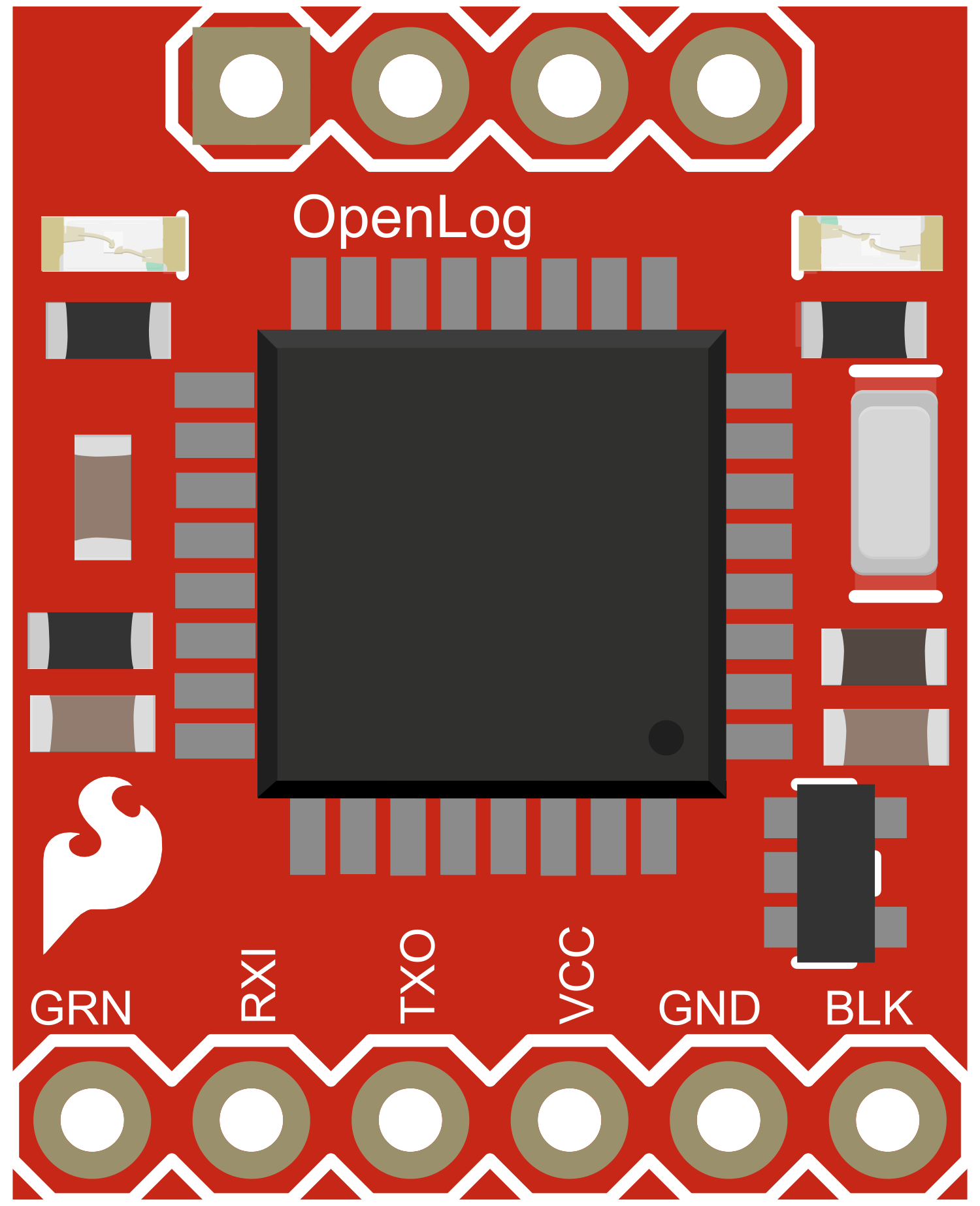
Pin Configuration and Descriptions

Pin # Name Description
1 GND Ground connection
2 VCC Power supply (3.3V to 12V)
3 RXI Serial Receive Input
4 TXO Serial Transmit Output
5 DTR Data Terminal Ready, used for automatic logging control

Usage Instructions

How to Use the Component in a Circuit

  1. Powering the OpenLog: Connect the VCC pin to a 3.3V to 12V power supply and the GND pin to the ground.
  2. Connecting to a Microcontroller: Connect the RXI pin of the OpenLog to the TX (transmit) pin of your microcontroller, and the TXO pin to the RX (receive) pin if bidirectional communication is required.
  3. Starting Logging: Insert a formatted microSD card into the OpenLog. The device will create a new log file automatically upon power-up and start logging any data received on the RXI pin.

Important Considerations and Best Practices

  • Ensure that the microSD card is formatted to FAT16 or FAT32 before use.
  • Use a level shifter if your microcontroller operates at a different logic level than 3.3V.
  • Avoid removing the microSD card or powering down the system while logging to prevent data corruption.
  • For high baud rates, ensure that the microcontroller and OpenLog are as close as possible to minimize signal degradation.

Troubleshooting and FAQs

Common Issues Users Might Face

  • Data not logging: Ensure that the microSD card is properly inserted and formatted. Check the connections between the OpenLog and the microcontroller.
  • Garbled data: Verify that the baud rate of the microcontroller matches the OpenLog setting. Check for noise in the serial line.
  • OpenLog not creating files: Make sure the DTR line is correctly connected if using automatic logging control.

Solutions and Tips for Troubleshooting

  • If the OpenLog is not behaving as expected, try resetting it by power cycling.
  • Check the OpenLog's LED indicators to diagnose power and logging status.
  • Ensure that the serial connection is not being interrupted by other processes on the microcontroller.

FAQs

Q: Can the OpenLog be used with sensors that do not have a serial output? A: Yes, but an intermediary microcontroller is required to read the sensor data and send it to the OpenLog via serial communication.

Q: What is the maximum size of the microSD card that can be used with the OpenLog? A: The OpenLog supports microSD cards up to 32GB in size.

Q: How do I change the baud rate of the OpenLog? A: The baud rate can be configured by editing the config.txt file on the microSD card or by sending serial commands to the OpenLog.

Example Code for Arduino UNO

Below is an example Arduino sketch that demonstrates how to send data to the OpenLog. This example assumes that the OpenLog is connected to the Arduino's hardware serial port.

#include <SoftwareSerial.h>

// Create a software serial port called 'openLog'
SoftwareSerial openLog(2, 3); // RX, TX

void setup() {
  // Start the hardware serial port for debugging
  Serial.begin(9600);
  // Start the software serial port at the baud rate of the OpenLog
  openLog.begin(9600);
  Serial.println("OpenLog test begins");
}

void loop() {
  // Send test data to the OpenLog
  openLog.println("Hello, OpenLog!");
  // Wait for 1 second
  delay(1000);
}

Remember to adjust the openLog.begin(9600); line to match the baud rate of your OpenLog if it is set to a different value.