Cirkit Designer Logo
Cirkit Designer
Your all-in-one circuit design IDE
Home / 
Component Documentation

How to Use Gravity: GNSS GPS BeiDou Positioning Module with RTC - I2C&UART: Examples, Pinouts, and Specs

Image of Gravity: GNSS GPS BeiDou Positioning Module with RTC - I2C&UART
Cirkit Designer LogoDesign with Gravity: GNSS GPS BeiDou Positioning Module with RTC - I2C&UART in Cirkit Designer

Introduction

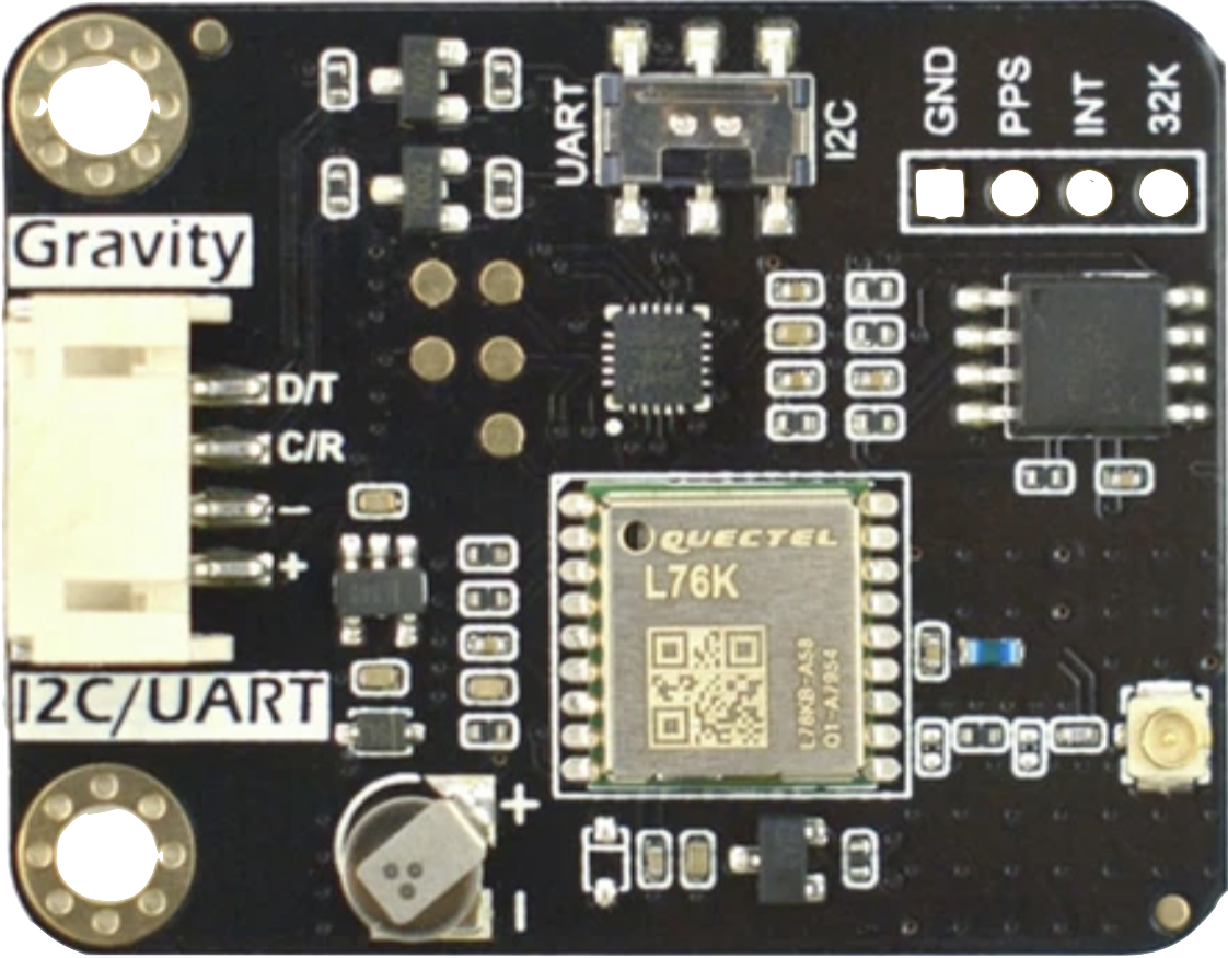
The Gravity: GNSS GPS BeiDou Positioning Module with RTC - I2C&UART (Manufacturer Part ID: DFR1103) is a high-performance positioning module developed by DFRobot. It leverages GNSS (Global Navigation Satellite System) technology, supporting both GPS and BeiDou systems, to deliver precise location data. Additionally, the module includes a Real-Time Clock (RTC) for accurate timekeeping, even when satellite signals are unavailable. Its dual communication interfaces, I2C and UART, make it versatile and easy to integrate into a wide range of embedded systems.

Explore Projects Built with Gravity: GNSS GPS BeiDou Positioning Module with RTC - I2C&UART

Use Cirkit Designer to design, explore, and prototype these projects online. Some projects support real-time simulation. Click "Open Project" to start designing instantly!
STM32F4-Based Multi-Sensor GPS Tracking System
Image of Phase 1 fc: A project utilizing Gravity: GNSS GPS BeiDou Positioning Module with RTC - I2C&UART in a practical application
This circuit integrates an STM32F4 microcontroller with a GPS module (NEO 6M), an accelerometer and gyroscope (MPU-6050), a barometric pressure sensor (BMP280), and a compass (HMC5883L). The microcontroller communicates with the sensors via I2C and the GPS module via UART, enabling it to gather and process environmental and positional data.
Cirkit Designer LogoOpen Project in Cirkit Designer
Dual RTC DS3231 Synchronization with Glyph C3 Microcontroller
Image of DS: A project utilizing Gravity: GNSS GPS BeiDou Positioning Module with RTC - I2C&UART in a practical application
This circuit integrates two RTC DS3231 real-time clock modules with a Glyph C3 microcontroller. The RTC modules are connected to the microcontroller via I2C communication protocol, using the SCL and SDA lines for clock and data respectively. Both RTC modules and the microcontroller share a common power supply (3V3) and ground (GND), indicating that they operate at the same voltage level.
Cirkit Designer LogoOpen Project in Cirkit Designer
Raspberry Pi Pico-Based Navigation Assistant with Bluetooth and GPS
Image of sat_dish: compass example: A project utilizing Gravity: GNSS GPS BeiDou Positioning Module with RTC - I2C&UART in a practical application
This circuit features a Raspberry Pi Pico microcontroller interfaced with an HC-05 Bluetooth module for wireless communication, an HMC5883L compass module for magnetic field measurement, and a GPS NEO 6M module for location tracking. The Pico is configured to communicate with the HC-05 via serial connection (TX/RX), with the compass module via I2C (SCL/SDA), and with the GPS module via serial (TX/RX). Common power (VCC) and ground (GND) lines are shared among all modules, indicating a unified power system.
Cirkit Designer LogoOpen Project in Cirkit Designer
Cellular-Enabled IoT Device with Real-Time Clock and Power Management
Image of LRCM PHASE 2 BASIC: A project utilizing Gravity: GNSS GPS BeiDou Positioning Module with RTC - I2C&UART in a practical application
This circuit features a LilyGo-SIM7000G module for cellular communication and GPS functionality, interfaced with an RTC DS3231 for real-time clock capabilities. It includes voltage sensing through two voltage sensor modules, and uses an 8-channel opto-coupler for isolating different parts of the circuit. Power management is handled by a buck converter connected to a DC power source and batteries, with a fuse for protection and a rocker switch for on/off control. Additionally, there's an LED for indication purposes.
Cirkit Designer LogoOpen Project in Cirkit Designer

Explore Projects Built with Gravity: GNSS GPS BeiDou Positioning Module with RTC - I2C&UART

Use Cirkit Designer to design, explore, and prototype these projects online. Some projects support real-time simulation. Click "Open Project" to start designing instantly!
Image of Phase 1 fc: A project utilizing Gravity: GNSS GPS BeiDou Positioning Module with RTC - I2C&UART in a practical application
STM32F4-Based Multi-Sensor GPS Tracking System
This circuit integrates an STM32F4 microcontroller with a GPS module (NEO 6M), an accelerometer and gyroscope (MPU-6050), a barometric pressure sensor (BMP280), and a compass (HMC5883L). The microcontroller communicates with the sensors via I2C and the GPS module via UART, enabling it to gather and process environmental and positional data.
Cirkit Designer LogoOpen Project in Cirkit Designer
Image of DS: A project utilizing Gravity: GNSS GPS BeiDou Positioning Module with RTC - I2C&UART in a practical application
Dual RTC DS3231 Synchronization with Glyph C3 Microcontroller
This circuit integrates two RTC DS3231 real-time clock modules with a Glyph C3 microcontroller. The RTC modules are connected to the microcontroller via I2C communication protocol, using the SCL and SDA lines for clock and data respectively. Both RTC modules and the microcontroller share a common power supply (3V3) and ground (GND), indicating that they operate at the same voltage level.
Cirkit Designer LogoOpen Project in Cirkit Designer
Image of sat_dish: compass example: A project utilizing Gravity: GNSS GPS BeiDou Positioning Module with RTC - I2C&UART in a practical application
Raspberry Pi Pico-Based Navigation Assistant with Bluetooth and GPS
This circuit features a Raspberry Pi Pico microcontroller interfaced with an HC-05 Bluetooth module for wireless communication, an HMC5883L compass module for magnetic field measurement, and a GPS NEO 6M module for location tracking. The Pico is configured to communicate with the HC-05 via serial connection (TX/RX), with the compass module via I2C (SCL/SDA), and with the GPS module via serial (TX/RX). Common power (VCC) and ground (GND) lines are shared among all modules, indicating a unified power system.
Cirkit Designer LogoOpen Project in Cirkit Designer
Image of LRCM PHASE 2 BASIC: A project utilizing Gravity: GNSS GPS BeiDou Positioning Module with RTC - I2C&UART in a practical application
Cellular-Enabled IoT Device with Real-Time Clock and Power Management
This circuit features a LilyGo-SIM7000G module for cellular communication and GPS functionality, interfaced with an RTC DS3231 for real-time clock capabilities. It includes voltage sensing through two voltage sensor modules, and uses an 8-channel opto-coupler for isolating different parts of the circuit. Power management is handled by a buck converter connected to a DC power source and batteries, with a fuse for protection and a rocker switch for on/off control. Additionally, there's an LED for indication purposes.
Cirkit Designer LogoOpen Project in Cirkit Designer

Common Applications

  • Navigation Systems: Ideal for robotics, drones, and autonomous vehicles.
  • Time Synchronization: Provides accurate time data for IoT devices and servers.
  • Geolocation Tracking: Suitable for asset tracking and outdoor positioning.
  • Weather Stations: Used for precise location and time data in environmental monitoring systems.

Technical Specifications

Key Technical Details

Parameter Specification
Power Supply Voltage 3.3V - 5.5V
Communication Interfaces I2C, UART
Positioning Systems GPS, BeiDou
Baud Rate (UART) Default: 9600 bps
I2C Address Default: 0x10
RTC Functionality Yes
Operating Temperature -40°C to 85°C
Dimensions 37mm x 22mm
Weight 5g

Pin Configuration and Descriptions

Pin Name Description
1 VCC Power input (3.3V - 5.5V). Connect to the power supply.
2 GND Ground. Connect to the ground of the circuit.
3 RX UART Receive pin. Connect to the TX pin of the microcontroller.
4 TX UART Transmit pin. Connect to the RX pin of the microcontroller.
5 SDA I2C Data line. Connect to the SDA pin of the microcontroller.
6 SCL I2C Clock line. Connect to the SCL pin of the microcontroller.
7 PPS Pulse Per Second output. Provides a precise timing pulse for synchronization.

Usage Instructions

How to Use the Module in a Circuit

  1. Power Connection: Connect the VCC pin to a 3.3V or 5V power source and the GND pin to the ground.
  2. Communication Interface:
    • For UART: Connect the RX and TX pins to the corresponding TX and RX pins of the microcontroller.
    • For I2C: Connect the SDA and SCL pins to the microcontroller's I2C data and clock lines, respectively.
  3. Antenna: Ensure the module's antenna has a clear view of the sky for optimal satellite reception.
  4. RTC Functionality: The RTC operates automatically and does not require additional configuration.
  5. Pulse Per Second (PPS): Use the PPS pin for precise timing applications if needed.

Important Considerations and Best Practices

  • Power Supply: Ensure a stable power supply within the specified voltage range to avoid damage to the module.
  • Antenna Placement: Place the antenna in an open area, away from obstructions and sources of interference.
  • UART Baud Rate: The default UART baud rate is 9600 bps. Adjust it in your microcontroller code if necessary.
  • I2C Address: The default I2C address is 0x10. Ensure no other devices on the I2C bus share the same address.

Example Code for Arduino UNO (Using I2C)

#include <Wire.h>

// I2C address of the GNSS module
#define GNSS_I2C_ADDRESS 0x10

void setup() {
  Serial.begin(9600); // Initialize serial communication for debugging
  Wire.begin();       // Initialize I2C communication

  Serial.println("GNSS Module Initialization...");
}

void loop() {
  Wire.beginTransmission(GNSS_I2C_ADDRESS); // Start communication with GNSS module
  Wire.write(0x00);                         // Request data (example command)
  Wire.endTransmission();

  Wire.requestFrom(GNSS_I2C_ADDRESS, 32);   // Request 32 bytes of data
  while (Wire.available()) {
    char c = Wire.read();                   // Read data byte by byte
    Serial.print(c);                        // Print received data to Serial Monitor
  }
  Serial.println();

  delay(1000); // Wait 1 second before the next request
}

Troubleshooting and FAQs

Common Issues and Solutions

  1. No Data Received from the Module:

    • Ensure the module is powered correctly (check VCC and GND connections).
    • Verify the communication interface (I2C or UART) is configured properly in your code.
    • Check the antenna placement for clear satellite reception.
  2. Incorrect or No Position Data:

    • Ensure the antenna has a clear view of the sky.
    • Wait for the module to acquire satellite signals (may take a few minutes initially).
  3. I2C Communication Fails:

    • Confirm the I2C address (default: 0x10) matches the address in your code.
    • Check the pull-up resistors on the I2C lines (if required).
  4. RTC Not Functioning:

    • The RTC requires no additional configuration. If it fails, ensure the module is powered correctly.

FAQs

  • Q: Can the module work indoors?
    A: The module is designed for outdoor use. Indoor operation may result in weak or no satellite signals.

  • Q: How accurate is the positioning data?
    A: The module provides positioning accuracy within a few meters under optimal conditions.

  • Q: Can I use both I2C and UART simultaneously?
    A: No, you must choose one communication interface at a time.

  • Q: What is the purpose of the PPS pin?
    A: The PPS pin outputs a precise timing pulse, useful for synchronization in time-sensitive applications.


This concludes the documentation for the Gravity: GNSS GPS BeiDou Positioning Module with RTC - I2C&UART. For further assistance, refer to the official DFRobot product page or contact their support team.